
Three-tier architecture is a well-established software application architecture that organizes applications into three logical and physical computing tiers: the presentation tier, or user interface; the application tier, where data is processed; and the data tier, where application data is stored and managed.
The chief benefit of three-tier architecture is that because each tier runs on its own infrastructure, each tier can be developed simultaneously by a separate development team. And can be updated or scaled as needed without impacting the other tiers.
For decades three-tier architecture was the prevailing architecture for client-server applications. Today, most three-tier applications are targets for modernization that uses cloud-native technologies such as containers and microservices and for migration to the cloud.
Connect and integrate your systems to prepare your infrastructure for AI.
Register for the guide on app modernization

Presentation tier
The presentation tier is the user interface and communication layer of the application, where the end user interacts with the application. Its main purpose is to display information to and collect information from the user. This top-level tier can run on a web browser, as desktop application, or a graphical user interface (GUI), for example. Web presentation tiers are developed by using HTML, CSS, and JavaScript. Desktop applications can be written in various languages depending on the platform.
Application tier
The application tier, also known as the logic tier or middle tier, is the heart of the application. In this tier, information that is collected in the presentation tier is processed - sometimes against other information in the data tier - using business logic, a specific set of business rules. The application tier can also add, delete, or modify data in the data tier.
The application tier is typically developed by using Python, Java, Perl, PHP or Ruby, and communicates with the data tier by using API calls.
The data tier, sometimes called database tier, data access tier or back-end, is where the information that is processed by the application is stored and managed. This can be a relational database management system such as PostgreSQL , MySQL, MariaDB, Oracle, Db2, Informix or Microsoft SQL Server, or in a NoSQL Database server such as Cassandra, CouchDB , or MongoDB .
In a three-tier application, all communication goes through the application tier. The presentation tier and the data tier cannot communicate directly with one another.
Tier versus layer
In discussions of three-tier architecture, layer is often used interchangeably – and mistakenly – for tier , as in 'presentation layer' or 'business logic layer'.
They aren't the same. A 'layer' refers to a functional division of the software, but a 'tier' refers to a functional division of the software that runs on infrastructure separate from the other divisions. The Contacts app on your phone, for example, is a three - layer application, but a single-tier application, because all three layers run on your phone.
The difference is important because layers can't offer the same benefits as tiers.
Again, the chief benefit of three-tier architecture is its logical and physical separation of functionality. Each tier can run on a separate operating system and server platform - for example, web server, application server, database server - that best fits its functional requirements. And each tier runs on at least one dedicated server hardware or virtual server, so the services of each tier can be customized and optimized without impacting the other tiers.
Other benefits (compared to single- or two-tier architecture) include:
- Faster development : Because each tier can be developed simultaneously by different teams, an organization can bring the application to market faster. And programmers can use the latest and best languages and tools for each tier.
- Improved scalability : Any tier can be scaled independently of the others as needed.
- Improved reliability : An outage in one tier is less likely to impact the availability or performance of the other tiers.
- Improved security : Because the presentation tier and data tier can't communicate directly, a well-designed application tier can function as an internal firewall, preventing SQL injections and other malicious exploits.
In web development, the tiers have different names but perform similar functions:
- The web server is the presentation tier and provides the user interface. This is usually a web page or website, such as an ecommerce site where the user adds products to the shopping cart, adds payment details or creates an account. The content can be static or dynamic, and is developed using HTML, CSS, and JavaScript.
- The application server corresponds to the middle tier, housing the business logic that is used to process user inputs. To continue the ecommerce example, this is the tier that queries the inventory database to return product availability, or adds details to a customer's profile. This layer often developed using Python, Ruby, or PHP and runs a framework such as Django, Rails, Symphony, or ASP.NET.
- The database server is the data or backend tier of a web application. It runs on database management software, such as MySQL, Oracle, DB2, or PostgreSQL.
While three-tier architecture is easily the most widely adopted multitier application architecture, there are others that you might encounter in your work or your research.
Two-tier architecture
Two-tier architecture is the original client-server architecture, consisting of a presentation tier and a data tier; the business logic lives in the presentation tier, the data tier or both. In two-tier architecture the presentation tier - and therefore the end user - has direct access to the data tier, and the business logic is often limited. A simple contact management application, where users can enter and retrieve contact data, is an example of a two-tier application.
N-tier architecture
N-tier architecture - also called or multitier architecture - refers to any application architecture with more than one tier. But applications with more than three layers are rare because extra layers offer few benefits and can make the application slower, harder to manage and more expensive to run. As a result, n-tier architecture and multitier architecture are usually synonyms for three-tier architecture.
Move to cloud faster with IBM Cloud Pak solutions running on Red Hat OpenShift software—integrated, open, containerized solutions certified by IBM®.
Seamlessly modernize your VMware workloads and applications with IBM Cloud.
Modernize, build new apps, reduce costs, and maximize ROI.
IBM Consulting® application modernization services, which are powered by IBM Consulting Cloud Accelerator, offers skills, methods, tools, and initiatives that help determine the right strategy based on your portfolio. To modernize and containerize legacy system applications and accelerate the time-to-value of hybrid cloud environments.
Discover what application modernization is, the common benefits and challenges, and how to get started.
Learn about how relational databases work and how they compare to other data storage options.
Explore cloud native applications and how they drive innovation and speed within your enterprise.
Modernize your legacy three-tier applications on your journey to cloud. Whether you need assistance with strategy, processes, or capabilities—or want full-service attention—IBM can help. Start using containerized middleware that can run in any cloud—all bundled in IBM Cloud Paks.
The OSI Model – The 7 Layers of Networking Explained in Plain English

This article explains the Open Systems Interconnection (OSI) model and the 7 layers of networking, in plain English.
The OSI model is a conceptual framework that is used to describe how a network functions. In plain English, the OSI model helped standardize the way computer systems send information to each other.
Learning networking is a bit like learning a language - there are lots of standards and then some exceptions. Therefore, it’s important to really understand that the OSI model is not a set of rules. It is a tool for understanding how networks function.
Once you learn the OSI model, you will be able to further understand and appreciate this glorious entity we call the Internet, as well as be able to troubleshoot networking issues with greater fluency and ease.
All hail the Internet!
Prerequisites
You don’t need any prior programming or networking experience to understand this article. However, you will need:
- Basic familiarity with common networking terms (explained below)
- A curiosity about how things work :)
Learning Objectives
Over the course of this article, you will learn:
- What the OSI model is
- The purpose of each of the 7 layers
- The problems that can happen at each of the 7 layers
- The difference between TCP/IP model and the OSI model
Common Networking Terms
Here are some common networking terms that you should be familiar with to get the most out of this article. I’ll use these terms when I talk about OSI layers next.
A node is a physical electronic device hooked up to a network, for example a computer, printer, router, and so on. If set up properly, a node is capable of sending and/or receiving information over a network.
Nodes may be set up adjacent to one other, wherein Node A can connect directly to Node B, or there may be an intermediate node, like a switch or a router, set up between Node A and Node B.
Typically, routers connect networks to the Internet and switches operate within a network to facilitate intra-network communication. Learn more about hub vs. switch vs. router.
Here's an example:

For the nitpicky among us (yep, I see you), host is another term that you will encounter in networking. I will define a host as a type of node that requires an IP address. All hosts are nodes, but not all nodes are hosts. Please Tweet angrily at me if you disagree.
Links connect nodes on a network. Links can be wired, like Ethernet, or cable-free, like WiFi.
Links to can either be point-to-point, where Node A is connected to Node B, or multipoint, where Node A is connected to Node B and Node C.
When we’re talking about information being transmitted, this may also be described as a one-to-one vs. a one-to-many relationship.
A protocol is a mutually agreed upon set of rules that allows two nodes on a network to exchange data.
“A protocol defines the rules governing the syntax (what can be communicated), semantics (how it can be communicated), and synchronization (when and at what speed it can be communicated) of the communications procedure. Protocols can be implemented on hardware, software, or a combination of both. Protocols can be created by anyone, but the most widely adopted protocols are based on standards.” - The Illustrated Network.
Both wired and cable-free links can have protocols.
While anyone can create a protocol, the most widely adopted protocols are often based on standards published by Internet organizations such as the Internet Engineering Task Force (IETF).
A network is a general term for a group of computers, printers, or any other device that wants to share data.
Network types include LAN, HAN, CAN, MAN, WAN, BAN, or VPN. Think I’m just randomly rhyming things with the word can ? I can ’t say I am - these are all real network types. Learn more here .
Topology describes how nodes and links fit together in a network configuration, often depicted in a diagram. Here are some common network topology types:

A network consists of nodes, links between nodes, and protocols that govern data transmission between nodes.
At whatever scale and complexity networks get to, you will understand what’s happening in all computer networks by learning the OSI model and 7 layers of networking.
What is the OSI Model?
The OSI model consists of 7 layers of networking.
First, what’s a layer?

No, a layer - not a lair . Here there are no dragons.
A layer is a way of categorizing and grouping functionality and behavior on and of a network.
In the OSI model, layers are organized from the most tangible and most physical, to less tangible and less physical but closer to the end user.
Each layer abstracts lower level functionality away until by the time you get to the highest layer. All the details and inner workings of all the other layers are hidden from the end user.
How to remember all the names of the layers? Easy.
- Please | Physical Layer
- Do | Data Link Layer
- Not | Network Layer
- Tell (the) | Transport Layer
- Secret | Session Layer
- Password (to) | Presentation Layer
- Anyone | Application Layer
Keep in mind that while certain technologies, like protocols, may logically “belong to” one layer more than another, not all technologies fit neatly into a single layer in the OSI model. For example, Ethernet, 802.11 (Wifi) and the Address Resolution Protocol (ARP) procedure operate on >1 layer.
The OSI is a model and a tool, not a set of rules.
OSI Layer 1
Layer 1 is the physical layer . There’s a lot of technology in Layer 1 - everything from physical network devices, cabling, to how the cables hook up to the devices. Plus if we don’t need cables, what the signal type and transmission methods are (for example, wireless broadband).
Instead of listing every type of technology in Layer 1, I’ve created broader categories for these technologies. I encourage readers to learn more about each of these categories:
- Nodes (devices) and networking hardware components. Devices include hubs, repeaters, routers, computers, printers, and so on. Hardware components that live inside of these devices include antennas, amplifiers, Network Interface Cards (NICs), and more.
- Device interface mechanics. How and where does a cable connect to a device (cable connector and device socket)? What is the size and shape of the connector, and how many pins does it have? What dictates when a pin is active or inactive?
- Functional and procedural logic. What is the function of each pin in the connector - send or receive? What procedural logic dictates the sequence of events so a node can start to communicate with another node on Layer 2?
- Cabling protocols and specifications. Ethernet (CAT), USB, Digital Subscriber Line (DSL) , and more. Specifications include maximum cable length, modulation techniques, radio specifications, line coding, and bits synchronization (more on that below).
- Cable types. Options include shielded or unshielded twisted pair, untwisted pair, coaxial and so on. Learn more about cable types here .
- Signal type. Baseband is a single bit stream at a time, like a railway track - one-way only. Broadband consists of multiple bit streams at the same time, like a bi-directional highway.
- Signal transmission method (may be wired or cable-free). Options include electrical (Ethernet), light (optical networks, fiber optics), radio waves (802.11 WiFi, a/b/g/n/ac/ax variants or Bluetooth). If cable-free, then also consider frequency: 2.5 GHz vs. 5 GHz. If it’s cabled, consider voltage. If cabled and Ethernet, also consider networking standards like 100BASE-T and related standards.
The data unit on Layer 1 is the bit.
A bit the smallest unit of transmittable digital information. Bits are binary, so either a 0 or a 1. Bytes, consisting of 8 bits, are used to represent single characters, like a letter, numeral, or symbol.
Bits are sent to and from hardware devices in accordance with the supported data rate (transmission rate, in number of bits per second or millisecond) and are synchronized so the number of bits sent and received per unit of time remains consistent (this is called bit synchronization). The way bits are transmitted depends on the signal transmission method.
Nodes can send, receive, or send and receive bits. If they can only do one, then the node uses a simplex mode. If they can do both, then the node uses a duplex mode. If a node can send and receive at the same time, it’s full-duplex – if not, it’s just half-duplex.
The original Ethernet was half-duplex. Full-duplex Ethernet is an option now, given the right equipment.
How to Troubleshoot OSI Layer 1 Problems
Here are some Layer 1 problems to watch out for:
- Defunct cables, for example damaged wires or broken connectors
- Broken hardware network devices, for example damaged circuits
- Stuff being unplugged (...we’ve all been there)
If there are issues in Layer 1, anything beyond Layer 1 will not function properly.
Layer 1 contains the infrastructure that makes communication on networks possible.
It defines the electrical, mechanical, procedural, and functional specifications for activating, maintaining, and deactivating physical links between network devices. - Source
Fun fact: deep-sea communications cables transmit data around the world. This map will blow your mind: https://www.submarinecablemap.com/
And because you made it this far, here’s a koala:

OSI Layer 2
Layer 2 is the data link layer . Layer 2 defines how data is formatted for transmission, how much data can flow between nodes, for how long, and what to do when errors are detected in this flow.
In more official tech terms:
- Line discipline. Who should talk for how long? How long should nodes be able to transit information for?
- Flow control. How much data should be transmitted?
- Error control - detection and correction . All data transmission methods have potential for errors, from electrical spikes to dirty connectors. Once Layer 2 technologies tell network administrators about an issue on Layer 2 or Layer 1, the system administrator can correct for those errors on subsequent layers. Layer 2 is mostly concerned with error detection, not error correction. ( Source )
There are two distinct sublayers within Layer 2:
- Media Access Control (MAC): the MAC sublayer handles the assignment of a hardware identification number, called a MAC address, that uniquely identifies each device on a network. No two devices should have the same MAC address. The MAC address is assigned at the point of manufacturing. It is automatically recognized by most networks. MAC addresses live on Network Interface Cards (NICs). Switches keep track of all MAC addresses on a network. Learn more about MAC addresses on PC Mag and in this article . Learn more about network switches here .
- Logical Link Control (LLC): the LLC sublayer handles framing addressing and flow control. The speed depends on the link between nodes, for example Ethernet or Wifi.
The data unit on Layer 2 is a frame .
Each frame contains a frame header, body, and a frame trailer:
- Header: typically includes MAC addresses for the source and destination nodes.
- Body: consists of the bits being transmitted.
- Trailer: includes error detection information. When errors are detected, and depending on the implementation or configuration of a network or protocol, frames may be discarded or the error may be reported up to higher layers for further error correction. Examples of error detection mechanisms: Cyclic Redundancy Check (CRC) and Frame Check Sequence (FCS). Learn more about error detection techniques here .

Typically there is a maximum frame size limit, called an Maximum Transmission Unit, MTU. Jumbo frames exceed the standard MTU, learn more about jumbo frames here .
How to Troubleshoot OSI Layer 2 Problems
Here are some Layer 2 problems to watch out for:
- All the problems that can occur on Layer 1
- Unsuccessful connections (sessions) between two nodes
- Sessions that are successfully established but intermittently fail
- Frame collisions
The Data Link Layer allows nodes to communicate with each other within a local area network. The foundations of line discipline, flow control, and error control are established in this layer.
OSI Layer 3
Layer 3 is the network layer . This is where we send information between and across networks through the use of routers. Instead of just node-to-node communication, we can now do network-to-network communication.
Routers are the workhorse of Layer 3 - we couldn’t have Layer 3 without them. They move data packets across multiple networks.
Not only do they connect to Internet Service Providers (ISPs) to provide access to the Internet, they also keep track of what’s on its network (remember that switches keep track of all MAC addresses on a network), what other networks it’s connected to, and the different paths for routing data packets across these networks.
Routers store all of this addressing and routing information in routing tables.
Here’s a simple example of a routing table:

The data unit on Layer 3 is the data packet . Typically, each data packet contains a frame plus an IP address information wrapper. In other words, frames are encapsulated by Layer 3 addressing information.
The data being transmitted in a packet is also sometimes called the payload . While each packet has everything it needs to get to its destination, whether or not it makes it there is another story.
Layer 3 transmissions are connectionless, or best effort - they don't do anything but send the traffic where it’s supposed to go. More on data transport protocols on Layer 4.
Once a node is connected to the Internet, it is assigned an Internet Protocol (IP) address, which looks either like 172.16. 254.1 (IPv4 address convention) or like 2001:0db8:85a3:0000:0000:8a2e:0370:7334 (IPv6 address convention). Routers use IP addresses in their routing tables.
IP addresses are associated with the physical node’s MAC address via the Address Resolution Protocol (ARP), which resolves MAC addresses with the node’s corresponding IP address.
ARP is conventionally considered part of Layer 2, but since IP addresses don’t exist until Layer 3, it’s also part of Layer 3.
How to Troubleshoot OSI Layer 3 Problems
Here are some Layer 3 problems to watch out for:
- All the problems that can crop up on previous layers :)
- Faulty or non-functional router or other node
- IP address is incorrectly configured
Many answers to Layer 3 questions will require the use of command-line tools like ping , trace , show ip route , or show ip protocols . Learn more about troubleshooting on layer 1-3 here .
The Network Layer allows nodes to connect to the Internet and send information across different networks.
OSI Layer 4
Layer 4 is the transport layer . This where we dive into the nitty gritty specifics of the connection between two nodes and how information is transmitted between them. It builds on the functions of Layer 2 - line discipline, flow control, and error control.
This layer is also responsible for data packet segmentation, or how data packets are broken up and sent over the network.
Unlike the previous layer, Layer 4 also has an understanding of the whole message, not just the contents of each individual data packet. With this understanding, Layer 4 is able to manage network congestion by not sending all the packets at once.
The data units of Layer 4 go by a few names. For TCP, the data unit is a packet. For UDP, a packet is referred to as a datagram. I’ll just use the term data packet here for the sake of simplicity.
Transmission Control Protocol (TCP) and User Datagram Protocol (UDP) are two of the most well-known protocols in Layer 4.
TCP, a connection-oriented protocol, prioritizes data quality over speed.
TCP explicitly establishes a connection with the destination node and requires a handshake between the source and destination nodes when data is transmitted. The handshake confirms that data was received. If the destination node does not receive all of the data, TCP will ask for a retry.
TCP also ensures that packets are delivered or reassembled in the correct order. Learn more about TCP here .
UDP, a connectionless protocol, prioritizes speed over data quality. UDP does not require a handshake, which is why it’s called connectionless.
Because UDP doesn’t have to wait for this acknowledgement, it can send data at a faster rate, but not all of the data may be successfully transmitted and we’d never know.
If information is split up into multiple datagrams, unless those datagrams contain a sequence number, UDP does not ensure that packets are reassembled in the correct order. Learn more about UDP here .
TCP and UDP both send data to specific ports on a network device, which has an IP address. The combination of the IP address and the port number is called a socket.
Learn more about sockets here .
Learn more about the differences and similarities between these two protocols here .
How to Troubleshoot OSI Layer 4 Problems
Here are some Layer 4 problems to watch out for:
- Blocked ports - check your Access Control Lists (ACL) & firewalls
- Quality of Service (QoS) settings. QoS is a feature of routers/switches that can prioritize traffic, and they can really muck things up. Learn more about QoS here .
The Transport Layer provides end-to-end transmission of a message by segmenting a message into multiple data packets; the layer supports connection-oriented and connectionless communication.
OSI Layer 5
Layer 5 is the session layer . This layer establishes, maintains, and terminates sessions.
A session is a mutually agreed upon connection that is established between two network applications. Not two nodes! Nope, we’ve moved on from nodes. They were so Layer 4.
Just kidding, we still have nodes, but Layer 5 doesn’t need to retain the concept of a node because that’s been abstracted out (taken care of) by previous layers.
So a session is a connection that is established between two specific end-user applications. There are two important concepts to consider here:
- Client and server model: the application requesting the information is called the client, and the application that has the requested information is called the server.
- Request and response model: while a session is being established and during a session, there is a constant back-and-forth of requests for information and responses containing that information or “hey, I don’t have what you’re requesting.”
Sessions may be open for a very short amount of time or a long amount of time. They may fail sometimes, too.
Depending on the protocol in question, various failure resolution processes may kick in. Depending on the applications/protocols/hardware in use, sessions may support simplex, half-duplex, or full-duplex modes.
Examples of protocols on Layer 5 include Network Basic Input Output System (NetBIOS) and Remote Procedure Call Protocol (RPC), and many others.
From here on out (layer 5 and up), networks are focused on ways of making connections to end-user applications and displaying data to the user.
How to Troubleshoot OSI Layer 5 Problems
Here are some Layer 5 problems to watch out for:
- Servers are unavailable
- Servers are incorrectly configured, for example Apache or PHP configs
- Session failure - disconnect, timeout, and so on.
The Session Layer initiates, maintains, and terminates connections between two end-user applications. It responds to requests from the presentation layer and issues requests to the transport layer.
OSI Layer 6
Layer 6 is the presentation layer . This layer is responsible for data formatting, such as character encoding and conversions, and data encryption.
The operating system that hosts the end-user application is typically involved in Layer 6 processes. This functionality is not always implemented in a network protocol.
Layer 6 makes sure that end-user applications operating on Layer 7 can successfully consume data and, of course, eventually display it.
There are three data formatting methods to be aware of:
- American Standard Code for Information Interchange (ASCII): this 7-bit encoding technique is the most widely used standard for character encoding. One superset is ISO-8859-1, which provides most of the characters necessary for languages spoken in Western Europe.
- Extended Binary-Coded Decimal Interchange Code (EBDCIC): designed by IBM for mainframe usage. This encoding is incompatible with other character encoding methods.
- Unicode: character encodings can be done with 32-, 16-, or 8-bit characters and attempts to accommodate every known, written alphabet.
Learn more about character encoding methods in this article , and also here .
Encryption: SSL or TLS encryption protocols live on Layer 6. These encryption protocols help ensure that transmitted data is less vulnerable to malicious actors by providing authentication and data encryption for nodes operating on a network. TLS is the successor to SSL.
How to Troubleshoot OSI Layer 6 Problems
Here are some Layer 6 problems to watch out for:
- Non-existent or corrupted drivers
- Incorrect OS user access level
The Presentation Layer formats and encrypts data.
OSI Layer 7
Layer 7 is the application layer .
True to its name, this is the layer that is ultimately responsible for supporting services used by end-user applications. Applications include software programs that are installed on the operating system, like Internet browsers (for example, Firefox) or word processing programs (for example, Microsoft Word).
Applications can perform specialized network functions under the hood and require specialized services that fall under the umbrella of Layer 7.
Electronic mail programs, for example, are specifically created to run over a network and utilize networking functionality, such as email protocols, which fall under Layer 7.
Applications will also control end-user interaction, such as security checks (for example, MFA), identification of two participants, initiation of an exchange of information, and so on.
Protocols that operate on this level include File Transfer Protocol (FTP), Secure Shell (SSH), Simple Mail Transfer Protocol (SMTP), Internet Message Access Protocol (IMAP), Domain Name Service (DNS), and Hypertext Transfer Protocol (HTTP).
While each of these protocols serve different functions and operate differently, on a high level they all facilitate the communication of information. ( Source )
How to Troubleshoot OSI Layer 7 Problems
Here are some Layer 7 problems to watch out for:
- All issues on previous layers
- Incorrectly configured software applications
- User error (... we’ve all been there)
The Application Layer owns the services and functions that end-user applications need to work. It does not include the applications themselves.
Our Layer 1 koala is all grown up.

Learning check - can you apply makeup to a koala?
Don’t have a koala?
Well - answer these questions instead. It’s the next best thing, I promise.
- What is the OSI model?
- What are each of the layers?
- How could I use this information to troubleshoot networking issues?
Congratulations - you’ve taken one step farther to understanding the glorious entity we call the Internet.
Learning Resources
Many, very smart people have written entire books about the OSI model or entire books about specific layers. I encourage readers to check out any O’Reilly-published books about the subject or about network engineering in general.
Here are some resources I used when writing this article:
- The Illustrated Network, 2nd Edition
- Protocol Data Unit (PDU): https://www.geeksforgeeks.org/difference-between-segments-packets-and-frames/
- Troubleshooting Along the OSI Model: https://www.pearsonitcertification.com/articles/article.aspx?p=1730891
- The OSI Model Demystified: https://www.youtube.com/watch?v=HEEnLZV2wGI
- OSI Model for Dummies: https://www.dummies.com/programming/networking/layers-in-the-osi-model-of-a-computer-network/
Chloe Tucker is an artist and computer science enthusiast based in Portland, Oregon. As a former educator, she's continuously searching for the intersection of learning and teaching, or technology and art. Reach out to her on Twitter @_chloetucker and check out her website at chloe.dev .
Read more posts .
If you read this far, thank the author to show them you care. Say Thanks
Learn to code for free. freeCodeCamp's open source curriculum has helped more than 40,000 people get jobs as developers. Get started
Home > Learning Center > OSI Model
Article's content

Need help protecting your applications?
See how imperva can help, what is the osi model.
The Open Systems Interconnection (OSI) model describes seven layers that computer systems use to communicate over a network. It was the first standard model for network communications, adopted by all major computer and telecommunication companies in the early 1980s
The modern Internet is not based on OSI, but on the simpler TCP/IP model. However, the OSI 7-layer model is still widely used, as it helps visualize and communicate how networks operate, and helps isolate and troubleshoot networking problems.
OSI was introduced in 1983 by representatives of the major computer and telecom companies, and was adopted by ISO as an international standard in 1984.
OSI Model Explained: The OSI 7 Layers

We’ll describe OSI layers “top down” from the application layer that directly serves the end user, down to the physical layer.
7. Application Layer
The application layer is used by end-user software such as web browsers and email clients. It provides protocols that allow software to send and receive information and present meaningful data to users. A few examples of application layer protocols are the Hypertext Transfer Protocol (HTTP), File Transfer Protocol (FTP), Post Office Protocol (POP), Simple Mail Transfer Protocol (SMTP), and Domain Name System (DNS).
6. Presentation Layer
The presentation layer prepares data for the application layer. It defines how two devices should encode, encrypt, and compress data so it is received correctly on the other end. The presentation layer takes any data transmitted by the application layer and prepares it for transmission over the session layer.
5. Session Layer
The session layer creates communication channels, called sessions, between devices. It is responsible for opening sessions, ensuring they remain open and functional while data is being transferred, and closing them when communication ends. The session layer can also set checkpoints during a data transfer—if the session is interrupted, devices can resume data transfer from the last checkpoint.
4. Transport Layer
The transport layer takes data transferred in the session layer and breaks it into “segments” on the transmitting end. It is responsible for reassembling the segments on the receiving end, turning it back into data that can be used by the session layer. The transport layer carries out flow control, sending data at a rate that matches the connection speed of the receiving device, and error control, checking if data was received incorrectly and if not, requesting it again.
3. Network Layer
The network layer has two main functions. One is breaking up segments into network packets, and reassembling the packets on the receiving end. The other is routing packets by discovering the best path across a physical network. The network layer uses network addresses (typically Internet Protocol addresses) to route packets to a destination node.
2. Data Link Layer
The data link layer establishes and terminates a connection between two physically-connected nodes on a network. It breaks up packets into frames and sends them from source to destination. This layer is composed of two parts—Logical Link Control (LLC), which identifies network protocols, performs error checking and synchronizes frames, and Media Access Control (MAC) which uses MAC addresses to connect devices and define permissions to transmit and receive data.
1. Physical Layer
The physical layer is responsible for the physical cable or wireless connection between network nodes. It defines the connector, the electrical cable or wireless technology connecting the devices, and is responsible for transmission of the raw data, which is simply a series of 0s and 1s, while taking care of bit rate control.
Advantages of OSI Model
The OSI model helps users and operators of computer networks:
- Determine the required hardware and software to build their network.
- Understand and communicate the process followed by components communicating across a network.
- Perform troubleshooting, by identifying which network layer is causing an issue and focusing efforts on that layer.
The OSI model helps network device manufacturers and networking software vendors:
- Create devices and software that can communicate with products from any other vendor, allowing open interoperability
- Define which parts of the network their products should work with.
- Communicate to users at which network layers their product operates – for example, only at the application layer, or across the stack.

PCI DSS 4.0 – the New Client-Side Security Frontier
Register Now
OSI vs. TCP/IP Model

The Transfer Control Protocol/Internet Protocol (TCP/IP) is older than the OSI model and was created by the US Department of Defense (DoD). A key difference between the models is that TCP/IP is simpler, collapsing several OSI layers into one:
- OSI layers 5, 6, 7 are combined into one Application Layer in TCP/IP
- OSI layers 1, 2 are combined into one Network Access Layer in TCP/IP – however TCP/IP does not take responsibility for sequencing and acknowledgement functions, leaving these to the underlying transport layer.
Other important differences:
- TCP/IP is a functional model designed to solve specific communication problems, and which is based on specific, standard protocols. OSI is a generic, protocol-independent model intended to describe all forms of network communication.
- In TCP/IP, most applications use all the layers, while in OSI simple applications do not use all seven layers. Only layers 1, 2 and 3 are mandatory to enable any data communication.
See how Imperva Web Application Firewall can help you with application security.
Imperva Application Security
Imperva security solutions secure your applications across multiple layers of the OSI model, from the network layer, protected by Imperva DDoS mitigation, to Imperva’s web application firewall (WAF), bot management and API security technology that safeguards the application layer.
To secure applications and networks across the OSI stack, Imperva provides multi-layered protection to make sure websites and applications are available, easily accessible and safe. The Imperva applicati on security solution includes:
- DDoS Protection —maintain uptime in all situations. Prevent any type of DDoS attack, of any size, from preventing access to your website and network infrastructure.
- CDN —enhance website performance and reduce bandwidth costs with a CDN designed for developers. Cache static resources at the edge while accelerating APIs and dynamic websites.
- WAF —cloud-based solution permits legitimate traffic and prevents bad traffic, safeguarding applications at the edge. Gateway WAF keeps applications and APIs inside your network safe.
- Bot protection —analyzes your bot traffic to pinpoint anomalies, identifies bad bot behavior and validates it via challenge mechanisms that do not impact user traffic.
- API security —protects APIs by ensuring only desired traffic can access your API endpoint, as well as detecting and blocking exploits of vulnerabilities.
- Account takeover protection —uses an intent-based detection process to identify and defends against attempts to take over users’ accounts for malicious purposes.
- RASP —keep your applications safe from within against known and zero‑day attacks. Fast and accurate protection with no signature or learning mode.
- Attack analytics —mitigate and respond to real cyber security threats efficiently and accurately with actionable intelligence across all your layers of defense.
Latest Blogs

Nadav Avital
Apr 4, 2024 2 min read

Mar 28, 2024 4 min read

Daniel Johnston
, Yohann Sillam
Mar 20, 2024 3 min read

Feb 19, 2024 6 min read

Jan 11, 2024 5 min read

, Sofia Naer
Dec 19, 2023 2 min read

Dec 14, 2023 5 min read

Dec 14, 2023 3 min read
Latest Articles
- Cybersecurity 101
188.4k Views
119.8k Views
117.4k Views
116.7k Views
98.5k Views
80.5k Views
58.6k Views
57.7k Views
2024 Bad Bot Report
Bad bots now represent almost one-third of all internet traffic
The State of API Security in 2024
Learn about the current API threat landscape and the key security insights for 2024
Protect Against Business Logic Abuse
Identify key capabilities to prevent attacks targeting your business logic
The State of Security Within eCommerce in 2022
Learn how automated threats and API attacks on retailers are increasing
Prevoty is now part of the Imperva Runtime Protection
Protection against zero-day attacks
No tuning, highly-accurate out-of-the-box
Effective against OWASP top 10 vulnerabilities
An Imperva security specialist will contact you shortly.
Top 3 US Retailer
- I Tried Both: Apple Watch 9 vs Fitbit Charge 6
- Best Places to Print Photos Online
The Layers of the OSI Model Illustrated
Each layer explained
- Massachusetts Institute of Technology
- University of Illinois
:max_bytes(150000):strip_icc():format(webp)/image-5e6611aebe974bb7886a24b5070c834f.jpg "presentation layer vs application layer")
- The Wireless Connection
- Routers & Firewalls
- Network Hubs
- Installing & Upgrading
- Wi-Fi & Wireless
The Open Systems Interconnection (OSI) model defines a networking framework to implement protocols in layers, with control passed from one layer to the next. It is primarily used today as a teaching tool. It conceptually divides computer network architecture into 7 layers in a logical progression.
The lower layers deal with electrical signals, chunks of binary data , and routing of these data across networks. Higher levels cover network requests and responses, representation of data, and network protocols, as seen from a user's point of view.
The OSI model was originally conceived as a standard architecture for building network systems, and many popular network technologies today reflect the layered design of OSI.
Physical Layer
At Layer 1, the Physical layer of the OSI model is responsible for the ultimate transmission of digital data bits from the Physical layer of the sending (source) device over network communications media to the Physical layer of the receiving (destination) device.
Examples of layer 1 technologies include Ethernet cables and hubs . Also, hubs and other repeaters are standard network devices that function at the Physical layer, as are cable connectors.
At the Physical layer, data is transmitted using the type of signaling supported by the physical medium: electric voltages, radio frequencies, or pulses of infrared or ordinary light.
Data Link Layer
When obtaining data from the Physical layer, the Data Link layer checks for physical transmission errors and packages bits into data frames. The Data Link layer also manages physical addressing schemes such as MAC addresses for Ethernet networks, controlling access of network devices to the physical medium.
Because the Data Link layer is the most complex layer in the OSI model, it is often divided into two parts: the Media Access Control sub-layer and the Logical Link Control sub-layer.
Network Layer
The Network layer adds the concept of routing above the Data Link layer. When data arrives at the Network layer, the source and destination addresses contained inside each frame are examined to determine if the data has reached its final destination. If the data has reached the final destination, layer 3 formats the data into packets delivered to the Transport layer. Otherwise, the Network layer updates the destination address and pushes the frame down to the lower layers.
To support routing, the Network layer maintains logical addresses such as IP addresses for devices on the network. The Network layer also manages the mapping between these logical addresses and physical addresses. In IPv4 networking, this mapping is accomplished through the Address Resolution Protocol (ARP); IPv6 uses Neighbor Discovery Protocol (NDP).
Transport Layer
The Transport Layer delivers data across network connections. TCP (Transmission Control Protocol) and UDP (User Datagram Protocol) are the most common examples of Transport Layer 4 network protocols. Different transport protocols may support a range of optional capabilities, including error recovery, flow control, and support for re-transmission.
Session Layer
The Session Layer manages the sequence and flow of events that initiate and tear down network connections. At layer 5, it is built to support multiple types of connections that can be created dynamically and run over individual networks.
Presentation Layer
The Presentation layer has the simplest function of any piece of the OSI model. At layer 6, it handles syntax processing of message data such as format conversions and encryption/decryption needed to support the Application layer above it.
Application Layer
The Application layer supplies network services to end-user applications. Network services are protocols that work with the user's data. For example, in a web browser application, the Application layer protocol HTTP packages the data needed to send and receive web page content. This layer 7 provides data to (and obtains data from) the Presentation layer.
Get the Latest Tech News Delivered Every Day
- Common Questions and Answers on the OSI Network Model
- A Guide to X.25 in Computer Networking
- OSI Model Reference Guide
- Cat5 vs. Cat6 Cable: What's the Difference?
- Visual Index of Computer Networking Topics
- Wireless Access Point vs. Wireless Application Protocol
- Understanding Transmission Control Protocol/Internet Protocol (TCP/IP)
- Here's Why Your Network Might Need a Layer 3 Switch
- What Is PPTP: Point-to-Point Tunneling Protocol
- What Are Network Protocols?
- How Do Computer Network Protocols Work?
- Beginner's Guide to Asynchronous Transfer Mode (ATM)
- ARP (Address Resolution Protocol) and Your Computer Network
- What Is a Virtual LAN (VLAN)?
- Use a Bridge to Expand Your Local Network
- A Short Guide on Networking Fundamentals

Web Application Architecture: How the Web Works
- Engineering
- 25 Jul, 2019
- No comments Share
What is Web Application Architecture?
- addresses a particular problem, even if it’s simply finding some information
- is as interactive as a desktop application
- has a Content Management System
How does the web request work?

Web request-response cycle
Web application architecture components and Three-Tier Architecture

Web application architecture following the three-tier pattern
Presentation layer
Business layer, persistence layer, example #1. dynamic web pages, spas, and mpas, single page applications.

Single Page Application architecture
Multi-Page Applications

MPA architecture
Example #2. Enterprise applications

Enterprise application architecture
To conclude
- Engineering Mathematics
- Discrete Mathematics
- Operating System
- Computer Networks
- Digital Logic and Design
- C Programming
- Data Structures
- Theory of Computation
- Compiler Design
- Computer Org and Architecture
- Computer Network Tutorial
Basics of Computer Network
- Basics of Computer Networking
- Introduction to basic Networking Terminology
- Goals of Networks
- Basic characteristics of Computer Networks
- Challenges of Computer Network
- Physical Components of Computer Network
Network Hardware and Software
- Types of Computer Networks
- LAN Full Form
- How to Set Up a LAN Network?
- MAN Full Form in Computer Networking
- MAN Full Form
- WAN Full Form
- Introduction of Internetworking
- Difference between Internet, Intranet and Extranet
- Protocol Hierarchies in Computer Network
- Network Devices (Hub, Repeater, Bridge, Switch, Router, Gateways and Brouter)
- Introduction of a Router
- Introduction of Gateways
- What is a network switch, and how does it work?
Network Topology
- Types of Network Topology
- Difference between Physical and Logical Topology
- What is OSI Model? - Layers of OSI Model
- Physical Layer in OSI Model
- Data Link Layer
- Session Layer in OSI model
- Presentation Layer in OSI model
Application Layer in OSI Model
- Protocol and Standard in Computer Networks
- Examples of Data Link Layer Protocols
- TCP/IP Model
- TCP/IP Ports and Its Applications
- What is Transmission Control Protocol (TCP)?
- TCP 3-Way Handshake Process
- Services and Segment structure in TCP
- TCP Connection Establishment
- TCP Connection Termination
- Fast Recovery Technique For Loss Recovery in TCP
- Difference Between OSI Model and TCP/IP Model
Medium Access Control
- MAC Full Form
- Channel Allocation Problem in Computer Network
- Multiple Access Protocols in Computer Network
- Carrier Sense Multiple Access (CSMA)
- Collision Detection in CSMA/CD
- Controlled Access Protocols in Computer Network
SLIDING WINDOW PROTOCOLS
- Stop and Wait ARQ
- Sliding Window Protocol | Set 3 (Selective Repeat)
- Piggybacking in Computer Networks
IP Addressing
- What is IPv4?
- What is IPv6?
- Introduction of Classful IP Addressing
- Classless Addressing in IP Addressing
- Classful Vs Classless Addressing
- Classless Inter Domain Routing (CIDR)
- Supernetting in Network Layer
- Introduction To Subnetting
- Difference between Subnetting and Supernetting
- Types of Routing
- Difference between Static and Dynamic Routing
- Unicast Routing - Link State Routing
- Distance Vector Routing (DVR) Protocol
- Fixed and Flooding Routing algorithms
- Introduction of Firewall in Computer Network
Congestion Control Algorithms
- Congestion Control in Computer Networks
- Congestion Control techniques in Computer Networks
- Computer Network | Leaky bucket algorithm
- TCP Congestion Control
Network Switching
- Circuit Switching in Computer Network
- Message switching techniques
- Packet Switching and Delays in Computer Network
- Differences Between Virtual Circuits and Datagram Networks
Application Layer:DNS
- Domain Name System (DNS) in Application Layer
- Details on DNS
- Introduction to Electronic Mail
- E-Mail Format
- World Wide Web (WWW)
- HTTP Full Form
- Streaming Stored Video
- What is a Content Distribution Network and how does it work?
CN Interview Quetions
- Top 50 Networking Interview Questions (2024)
- Top 50 TCP/IP Interview Questions and Answers 2024
- Top 50 IP Addressing Interview Questions and Answers
- Last Minute Notes - Computer Networks
- Computer Network - Cheat Sheet
- Network Layer
- Transport Layer
- Application Layer
Prerequisite : OSI Model
Introduction : The Application Layer is topmost layer in the Open System Interconnection (OSI) model. This layer provides several ways for manipulating the data (information) which actually enables any type of user to access network with ease. This layer also makes a request to its bottom layer, which is presentation layer for receiving various types of information from it. The Application Layer interface directly interacts with application and provides common web application services. This layer is basically highest level of open system, which provides services directly for application process.
Functions of Application Layer : The Application Layer, as discussed above, being topmost layer in OSI model, performs several kinds of functions which are requirement in any kind of application or communication process. Following are list of functions which are performed by Application Layer of OSI Model –
- Application Layer provides a facility by which users can forward several emails and it also provides a storage facility.
- This layer allows users to access, retrieve and manage files in a remote computer.
- It allows users to log on as a remote host.
- This layer provides access to global information about various services.
- This layer provides services which include: e-mail, transferring files, distributing results to the user, directory services, network resources and so on.
- It provides protocols that allow software to send and receive information and present meaningful data to users.
- It handles issues such as network transparency, resource allocation and so on.
- This layer serves as a window for users and application processes to access network services.
- Application Layer is basically not a function, but it performs application layer functions.
- The application layer is actually an abstraction layer that specifies the shared protocols and interface methods used by hosts in a communication network.
- Application Layer helps us to identify communication partners, and synchronizing communication.
- This layer allows users to interact with other software applications.
- In this layer, data is in visual form, which makes users truly understand data rather than remembering or visualize the data in the binary format (0’s or 1’s).
- This application layer basically interacts with Operating System (OS) and thus further preserves the data in a suitable manner.
- This layer also receives and preserves data from it’s previous layer, which is Presentation Layer (which carries in itself the syntax and semantics of the information transmitted).
- The protocols which are used in this application layer depend upon what information users wish to send or receive.
- This application layer, in general, performs host initialization followed by remote login to hosts.
Working of Application Layer in the OSI model : In the OSI model, this application layer is narrower in scope. The application layer in the OSI model generally acts only like the interface which is responsible for communicating with host-based and user-facing applications. This is in contrast with TCP/IP protocol, wherein the layers below the application layer, which is Session Layer and Presentation layer, are clubbed together and form a simple single layer which is responsible for performing the functions, which includes controlling the dialogues between computers, establishing as well as maintaining as well as ending a particular session, providing data compression and data encryption and so on.
At first, client sends a command to server and when server receives that command, it allocates port number to client. Thereafter, the client sends an initiation connection request to server and when server receives request, it gives acknowledgement (ACK) to client through client has successfully established a connection with the server and, therefore, now client has access to server through which it may either ask server to send any types of files or other documents or it may upload some files or documents on server itself.
Features provided by Application Layer Protocols : To ensure smooth communication, application layer protocols are implemented the same on source host and destination host. The following are some of the features which are provided by Application layer protocols-
- The Application Layer protocol defines process for both parties which are involved in communication.
- These protocols define the type of message being sent or received from any side (either source host or destination host).
- These protocols also define basic syntax of the message being forwarded or retrieved.
- These protocols define the way to send a message and the expected response.
- These protocols also define interaction with the next level.
Application Layer Protocols: The application layer provides several protocols which allow any software to easily send and receive information and present meaningful data to its users. The following are some of the protocols which are provided by the application layer.
- TELNET: Telnet stands for Telecommunications Network. This protocol is used for managing files over the Internet. It allows the Telnet clients to access the resources of Telnet server. Telnet uses port number 23.
- DNS: DNS stands for Domain Name System. The DNS service translates the domain name (selected by user) into the corresponding IP address. For example- If you choose the domain name as www.abcd.com, then DNS must translate it as 192.36.20.8 (random IP address written just for understanding purposes). DNS protocol uses the port number 53.
- DHCP: DHCP stands for Dynamic Host Configuration Protocol. It provides IP addresses to hosts. Whenever a host tries to register for an IP address with the DHCP server, DHCP server provides lots of information to the corresponding host. DHCP uses port numbers 67 and 68.
- FTP: FTP stands for File Transfer Protocol. This protocol helps to transfer different files from one device to another. FTP promotes sharing of files via remote computer devices with reliable, efficient data transfer. FTP uses port number 20 for data access and port number 21 for data control.
- SMTP: SMTP stands for Simple Mail Transfer Protocol. It is used to transfer electronic mail from one user to another user. SMTP is used by end users to send emails with ease. SMTP uses port numbers 25 and 587.
- HTTP: HTTP stands for Hyper Text Transfer Protocol. It is the foundation of the World Wide Web (WWW). HTTP works on the client server model. This protocol is used for transmitting hypermedia documents like HTML. This protocol was designed particularly for the communications between the web browsers and web servers, but this protocol can also be used for several other purposes. HTTP is a stateless protocol (network protocol in which a client sends requests to server and server responses back as per the given state), which means the server is not responsible for maintaining the previous client’s requests. HTTP uses port number 80.
- NFS: NFS stands for Network File System. This protocol allows remote hosts to mount files over a network and interact with those file systems as though they are mounted locally. NFS uses the port number 2049.
- SNMP: SNMP stands for Simple Network Management Protocol. This protocol gathers data by polling the devices from the network to the management station at fixed or random intervals, requiring them to disclose certain information. SNMP uses port numbers 161 (TCP) and 162 (UDP).

Please Login to comment...
Similar reads, improve your coding skills with practice.
What kind of Experience do you want to share?

Introducing Copilot+ PCs
May 20, 2024 | Yusuf Mehdi - Executive Vice President, Consumer Chief Marketing Officer
- Share on Facebook (opens new window)
- Share on Twitter (opens new window)
- Share on LinkedIn (opens new window)

An on-demand recording of our May 20 event is available .
Today, at a special event on our new Microsoft campus, we introduced the world to a new category of Windows PCs designed for AI, Copilot+ PCs.
Copilot+ PCs are the fastest, most intelligent Windows PCs ever built. With powerful new silicon capable of an incredible 40+ TOPS (trillion operations per second), all – day battery life and access to the most advanced AI models, Copilot+ PCs will enable you to do things you can’t on any other PC. Easily find and remember what you have seen in your PC with Recall, generate and refine AI images in near real-time directly on the device using Cocreator, and bridge language barriers with Live Captions, translating audio from 40+ languages into English .
These experiences come to life on a set of thin, light and beautiful devices from Microsoft Surface and our OEM partners Acer, ASUS, Dell, HP, Lenovo and Samsung, with pre-orders beginning today and availability starting on June 18. Starting at $999, Copilot+ PCs offer incredible value.
This first wave of Copilot+ PCs is just the beginning. Over the past year, we have seen an incredible pace of innovation of AI in the cloud with Copilot allowing us to do things that we never dreamed possible. Now, we begin a new chapter with AI innovation on the device. We have completely reimagined the entirety of the PC – from silicon to the operating system, the application layer to the cloud – with AI at the center, marking the most significant change to the Windows platform in decades.
YouTube Video
The fastest, most secure Windows PCs ever built
We introduced an all-new system architecture to bring the power of the CPU, GPU, and now a new high performance Neural Processing Unit (NPU) together. Connected to and enhanced by the large language models (LLMs) running in our Azure Cloud in concert with small language models (SLMs), Copilot+ PCs can now achieve a level of performance never seen before. They are up to 20x more powerful [1] and up to 100x as efficient [2] for running AI workloads and deliver industry-leading AI acceleration. They outperform Apple’s MacBook Air 15” by up to 58% in sustained multithreaded performance [3] , all while delivering all-day battery life. With incredible efficiency, Copilot+ PCs can deliver up to 22 hours of local video playback or 15 hours of web browsing on a single charge. [4] That is up to 20% more battery in local video playback than the MacBook Air 15”. [5]
Windows now has the best implementation of apps on the fastest chip, starting with Qualcomm. We now offer more native Arm64 experiences than ever before, including our fastest implementation of Microsoft 365 apps like Teams, PowerPoint, Outlook, Word, Excel, OneDrive and OneNote. Chrome, Spotify, Zoom, WhatsApp, Adobe Photoshop, Adobe Lightroom, Blender, Affinity Suite, DaVinci Resolve and many more now run natively on Arm to give you great performance with additional apps, like Slack, releasing later this year. In fact, 87% of the total app minutes people spend in apps today have native Arm versions. [6] With a powerful new emulator, Prism, your apps run great, whether native or emulated.
Every Copilot+ PC comes secured out of the box. The Microsoft Pluton Security processor will be enabled by default on all Copilot+ PCs and we have introduced a number of new features, updates and defaults to Windows 11 that make it easy for users to stay secure. And, we’ve built in personalized privacy controls to help you protect what’s important to you. You can read more about how we are making Windows more secure here .
Entirely new, powerful AI experiences
Copilot+ PCs leverage powerful processors and multiple state-of-the-art AI models, including several of Microsoft’s world-class SLMs, to unlock a new set of experiences you can run locally, directly on the device. This removes previous limitations on things like latency, cost and even privacy to help you be more productive, creative and communicate more effectively.
Recall instantly
We set out to solve one of the most frustrating problems we encounter daily – finding something we know we have seen before on our PC. Today, we must remember what file folder it was stored in, what website it was on, or scroll through hundreds of emails trying to find it.
Now with Recall, you can access virtually what you have seen or done on your PC in a way that feels like having photographic memory. Copilot+ PCs organize information like we do – based on relationships and associations unique to each of our individual experiences. This helps you remember things you may have forgotten so you can find what you’re looking for quickly and intuitively by simply using the cues you remember. [7]
You can scroll across time to find the content you need in your timeline across any application, website, document, or more. Interact intuitively using snapshots with screenray to help you take the next step using suggested actions based on object recognition. And get back to where you were, whether to a specific email in Outlook or the right chat in Teams.
Recall leverages your personal semantic index, built and stored entirely on your device. Your snapshots are yours; they stay locally on your PC. You can delete individual snapshots, adjust and delete ranges of time in Settings, or pause at any point right from the icon in the System Tray on your Taskbar. You can also filter apps and websites from ever being saved. You are always in control with privacy you can trust.
Cocreate with AI-powered image creation and editing, built into Windows
Since the launch of Image Creator, almost 10 billion images have been generated, helping more people bring their ideas to life easily by using natural language to describe what they want to create. Yet, today’s cloud offerings may limit the number of images you can create, keep you waiting while the artwork processes or even present privacy concerns. By using the Neural Processing Units (NPUs) and powerful local small language models, we are bringing innovative new experiences to your favorite creative applications like Paint and Photos.
Combine your ink strokes with text prompts to generate new images in nearly real time with Cocreator. As you iterate, so does the artwork, helping you more easily refine, edit and evolve your ideas. Powerful diffusion-based algorithms optimize for the highest quality output over minimum steps to make it feel like you are creating alongside AI. Use the creativity slider to choose from a range of artwork from more literal to more expressive. Once you select your artwork, you can continue iterating on top of it, helping you express your ideas, regardless of your creative skills.

Take photo editing and image creation to the next level. With Restyle Image, you can reimagine your personal photos with a new style combining image generation and photo editing in Photos. Use a pre-set style like Cyberpunk or Claymation to change the background, foreground or full picture to create an entirely new image. Or jumpstart your next creative project and get visual inspiration with Image Creator in Photos. On Copilot+ PCs you can generate endless images for free, fast, with the ability to fine tune images to your liking and to save your favorites to collections.
Innovative AI experiences from the creative apps you love
We are also partnering with some of the biggest and most-loved applications on the planet to leverage the power of the NPU to deliver new innovative AI experiences.
Together with Adobe, we are thrilled to announce Adobe’s flagship apps are coming to Copilot+ PCs, including Photoshop, Lightroom and Express – available today. Illustrator, Premiere Pro and more are coming this summer. And we’re continuing to partner to optimize AI in these apps for the NPU. For Adobe Creative Cloud customers, they will benefit from the full performance advantages of Copilot+ PCs to express their creativity faster than ever before.

DaVinci Resolve Studio
Effortlessly apply visual effects to objects and people using NPU-accelerated Magic Mask in DaVinci Resolve Studio.

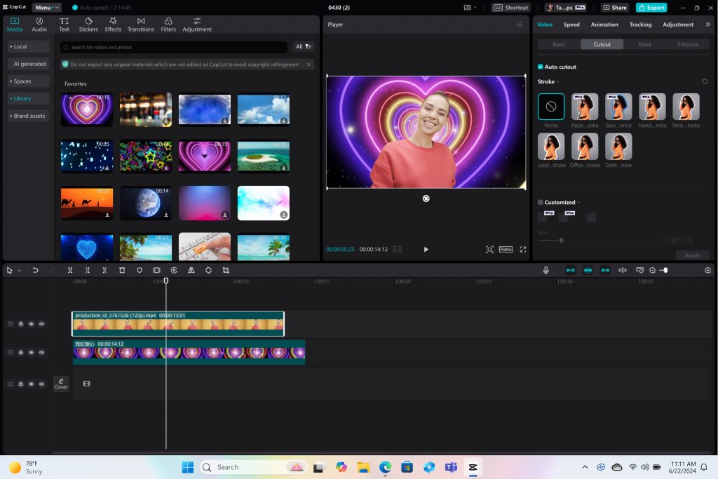
Remove the background from any video clip in a snap using Auto Cutout running on the NPU in CapCut.
Stay in your flow with faster, more responsive adaptive input controls, like head movement or facial expressions via the new NPU-powered camera pipeline in Cephable.

LiquidText
Make quicker and smarter annotations to documents, using AI features that run entirely on-device via NPU, so data stays private in LiquidText.

Have fun breaking down and remixing any music track, with a new, higher-quality version of NeuralMix™ that’s exclusive to NPU in Algoriddim’s djay Pro.

Connect and communicate effortlessly with live captions
In an increasingly connected and global world, Windows wants to bring people closer together. Whether catching up on your favorite podcast from a different country, or watching your favorite international sports team, or even collaborating with friends and colleagues across the world, we want to make more content accessible to more people.
Live Captions now has live translations and will turn any audio that passes through your PC into a single, English-language caption experience, in real time on your screen across all your apps consistently. You can translate any live or pre-recorded audio in any app or video platform from over 40 languages into English subtitles instantly, automatically and even while you’re offline. Powered by the NPU and available across all Copilot+ PCs, now you can have confidence your words are understood as intended.
New and enhanced Windows Studio Effects
Look and sound your best automatically with easily accessible controls at your fingertips in Quick Settings. Portrait light automatically adjusts the image to improve your perceived illumination in a dark environment or brighten the foreground pixels when in a low-light environment. Three new creative filters (illustrated, animated or watercolor) add an artistic flare. Eye contact teleprompter helps you maintain eye contact while reading your screen. New improvements to voice focus and portrait blur help ensure you’re always in focus.
Copilot, your everyday AI companion

Every Copilot+ PC comes with your personal powerful AI agent that is just a single tap away on keyboards with the new Copilot key. [8] Copilot will now have the full application experience customers have been asking for in a streamlined, simple yet powerful and personal design. Copilot puts the most advanced AI models at your fingertips. In the coming weeks, get access to the latest models including GPT-4o from our partners at OpenAI, so you can have voice conversations that feel more natural.
Advancing AI responsibly
At Microsoft, we have a company-wide commitment to develop ethical, safe and secure AI. Our responsible AI principles guided the development of these new experiences, and all AI features are aligned with our standards. Learn more here .
New Copilot+ PCs from Microsoft Surface and our partners
We have worked with each of the top OEMs — Acer, ASUS, Dell, HP, Lenovo, Samsung — and of course Surface, to bring exciting new Copilot+ PCs that will begin to launch on June 18. Starting at $999, these devices are up to $200 less than similar spec’d devices [9] .
Surface plays a key role in the Windows ecosystem, as we design software and hardware together to deliver innovative designs and meaningful experiences to our customers and fans. We are introducing the first-ever Copilot+ PCs from Surface: The all-new Surface Pro and Surface Laptop.

The new Surface Laptop is a powerhouse in an updated, modern laptop design with razor-thin bezels, a brilliant touchscreen display, AI-enhanced camera, premium audio, and now with a haptic touchpad.
Choose between a 13.8” and 15” display and four stunning colors. Enjoy up to 22 hours of local video playback on Surface Laptop 15” or up to 20 hours on Surface Laptop13.8” on top of incredible performance and all-new AI experiences.
The new Surface Pro is the most flexible 2-in-1 laptop, now reimagined with more speed and battery life to power all-new AI experiences. It introduces a new, optional OLED with HDR display, and ultrawide field of view camera perfect for Windows Studio Effects. The new Surface Pro Flex Keyboard is the first 2-in-1 keyboard designed to be used both attached or detached. It delivers enhanced stability, with Surface Slim Pen storage and charging integrated seamlessly, as well as a quiet, haptic touchpad. Learn more here.
New Copilot+ PCs from the biggest brands available starting June 18:
- Acer : Acer’s Swift 14 AI 2.5K touchscreen enables you to draw and edit your vision with greater accuracy and with color-accurate imagery. Launch and discover AI-enhanced features, like Acer PurifiedVoice 2.0 and Purified View, with a touch of the dedicated AcerSense button.
- ASUS : The ASUS Vivobook S 15 is a powerful device that brings AI experiences to life with its Snapdragon X Elite Platform and built-in Qualcomm® AI. It boasts 40+ NPU TOPS, a dual-fan cooling system, and up to 1 TB of storage. Next-gen AI enhancements include Windows Studio effects v2 and ASUS AiSense camera, with presence-detection capabilities for Adaptive Dimming and Lock. Built for portability, it has an ultra-slim and light all-metal design, a high-capacity battery, and premium styling with a single-zone RGB backlit keyboard.
- Dell : Dell is launching five new Copilot+ PCs, including the XPS 13, Inspiron 14 Plus, Inspiron 14, Latitude 7455, and Latitude 5455, offering a range of consumer and commercial options that deliver groundbreaking battery life and unique AI experiences. The XPS 13 is powered by Snapdragon X Elite processors and features a premium, futuristic design, while the Latitude 7455 boasts a stunning QHD+ display and quad speakers with AI noise reduction. The Inspiron14 and Inspiron 14 Plus feature a Snapdragon X Plus 1and are crafted with lightweight, low carbon aluminum and are energy efficient with EPEAT Gold rating.
- HP : HP’s OmniBook X AI PC and HP EliteBook Ultra G1q AI PC with Snapdragon X Elite are slim and sleek designs, delivering advanced performance and mobility for a more personalized computing experience. Features include long-lasting battery life and AI-powered productivity tools, such as real-time transcription and meeting summaries. A 5MP camera with automatic framing and eye focus is supported by Poly Studio’s crystal-clear audio for enhanced virtual interactions.
- Lenovo : Lenovo is launching two AI PCs: one built for consumers, Yoga Slim 7x, and one for commercial, ThinkPad T14s Gen 6. The Yoga Slim 7x brings efficiency for creatives, featuring a 14.5” touchscreen with 3K Dolby Vision and optimized power for 3D rendering and video editing. The T14s Gen 6 brings enterprise-level experiences and AI performance to your work tasks, with features including a webcam privacy shutter, Wi-Fi 7 connectivity and up to 64GB RAM.
- Samsung : Samsung’s new Galaxy Book4 Edge is ultra-thin and light, with a 3K resolution 2x AMOLED display and Wi-Fi 7 connectivity. It has a long-lasting battery that provides up to 22 hours of video playback, making it perfect for work or entertainment on the go.
Learn more about new Copilot+ PCs and pre-order today at Microsoft.com and from major PC manufacturers, as well as other leading global retailers.
Start testing for commercial deployment today
Copilot+ PCs offer businesses the most performant Windows 11 devices with unique AI capabilities to unlock productivity, improve collaboration and drive efficiency. As a Windows PC, businesses can deploy and manage a Copilot+ PC with the same tools and processes used today including IT controls for new features and AppAssure support. We recommend IT admins begin testing and readying for deployment to start empowering your workforce with access to powerful AI features on these high-performance devices. You can read more about our commercial experiences here .

AI innovation across the Windows ecosystem
Like we’ve always done with Windows, we have built a platform for our ecosystem partners to build on.
The first Copilot+ PCs will launch with both the Snapdragon® X Elite and Snapdragon® X Plus processors and feature leading performance per watt thanks to the custom Qualcomm Oryon™ CPU, which delivers unrivaled performance and battery efficiency. Snapdragon X Series delivers 45 NPU TOPS all-in-one system on a chip (SoC). The premium integrated Qualcomm® Adreno ™ GPU delivers stunning graphics for immersive entertainment. We look forward to expanding through deep partnerships with Intel and AMD, starting with Lunar Lake and Strix Point. We will bring new Copilot+ PC experiences at a later date. In the future we expect to see devices with this silicon paired with powerful graphics cards like NVIDIA GeForce RTX and AMD Radeon™, bringing Copilot+ PC experiences to reach even broader audiences like advanced gamers and creators.
We are at an inflection point where the PC will accelerate AI innovation. We believe the richest AI experiences will only be possible when the cloud and device work together in concert. Together with our partners, we’re setting the frame for the next decade of Windows innovation.
[1] Based on snapshot of aggregated, non-gaming app usage data as of April 2024 for iGPU-based laptops and 2-in-1 devices running Windows 10 and Windows 11 in US, UK, CA, FR, AU, DE, JP.
[2] Tested April 2024 using Phi SLM workload running 512-token prompt processing in a loop with default settings comparing pre-release Copilot+ PC builds with Snapdragon Elite X 12 Core and Snapdragon X Plus 10 core configurations (QNN build) to Windows 11 PC with NVIDIA 4080 GPU configuration (CUDA build).
[3] Tested May 2024 using Cinebench 2024 Multi-Core benchmark comparing Copilot+ PCs with Snapdragon X Elite 12 core and Snapdragon X Plus 10 core configurations to MacBook Air 15” with M3 8 core CPU / 10 Core GPU configuration. Performance will vary significantly between device configuration and usage.
[4] *Battery life varies significantly by device and with settings, usage and other factors. See aka.ms/cpclaims*
[5] *Battery life varies significantly based on device configuration, usage, network and feature configuration, signal strength, settings and other factors. Testing conducted May 2024 using the prelease Windows ADK full screen local video playback assessment under standard testing conditions, with the device connected to Wi-Fi and screen brightness set to 150 nits, comparing Copilot+ PCs with Snapdragon X Elite 12 core and Snapdragon X Plus 10 core configurations running Windows Version 26097.5003 (24H2) to MacBook Air 15” M3 8-Core CPU/ 10 Core GPU running macOS 14.4 with similar device configurations and testing scenario.
[6] Based on snapshot of aggregated, non-gaming app usage data as of April 2024 for iGPU-based laptops and 2-in-1 devices running Windows 10 and Windows 11 in US, UK, CA, FR, AU, DE, JP.
[7] Recall is optimized for select languages (English, Chinese (simplified), French, German, Japanese, and Spanish.) Content-based and storage limitations apply. Learn more here .
[8] Copilot key functionality may vary. See aka.ms/keysupport
[9] Based on MSRPs; actual savings may vary
Tags: AI , Copilot+ PC
- Check us out on RSS
IMAGES
VIDEO
COMMENTS
Here are five main layers in software architecture: 1. Presentation layer. The presentation layer, also called the UI layer, handles the interactions that users have with the software. It's the most visible layer and defines the application's overall look and presentation to the end-users. This is the tier that's most accessible, which anyone ...
In discussions of three-tier architecture, layer is often used interchangeably - and mistakenly - for tier, as in 'presentation layer' or 'business logic layer'. They aren't the same. A 'layer' refers to a functional division of the software, but a 'tier' refers to a functional division of the software that runs on infrastructure separate ...
The Session Layer initiates, maintains, and terminates connections between two end-user applications. It responds to requests from the presentation layer and issues requests to the transport layer. OSI Layer 6. Layer 6 is the presentation layer. This layer is responsible for data formatting, such as character encoding and conversions, and data ...
0. The presentation layer delivers information to the application layer for display. The presentation layer, in some cases, handles data translation to allow use on a particular system. The user interface shows you the data once the presentation layer has done any translations it needs to.
Prerequisite : OSI Model. Introduction : Presentation Layer is the 6th layer in the Open System Interconnection (OSI) model. This layer is also known as Translation layer, as this layer serves as a data translator for the network. The data which this layer receives from the Application Layer is extracted and manipulated here as per the required ...
6. Presentation Layer. The presentation layer prepares data for the application layer. It defines how two devices should encode, encrypt, and compress data so it is received correctly on the other end. The presentation layer takes any data transmitted by the application layer and prepares it for transmission over the session layer. 5. Session ...
The Presentation layer has the simplest function of any piece of the OSI model. At layer 6, it handles syntax processing of message data such as format conversions and encryption/decryption needed to support the Application layer above it. ... Application Layer . The Application layer supplies network services to end-user applications. Network ...
The presentation layer ensures the information that the application layer of one system sends out is readable by the application layer of another system. On the sending system it is responsible for conversion to standard, transmittable formats. [7] On the receiving system it is responsible for the translation, formatting, and delivery of ...
Web application architecture following the three-tier pattern. Presentation layer The presentation layer is accessible to users via a browser and consists of user interface components and UI process components that support interaction with the system. It's developed using three core technologies: HTML, CSS, and JavaScript.
The presentation layer is located at Layer 6 of the OSI model. The tool that manages Hypertext Transfer Protocol ( HTTP) is an example of a program that loosely adheres to the presentation layer of OSI. Although it's technically considered an application-layer protocol per the TCP/IP model, HTTP includes presentation layer services within it.
Layer 6: Presentation layer. To give you a hint of what this layer does, I can tell you that some people recognize L6 by a different name — The translation layer! Similar to human translators, L6 translates data that is coming from L5 so that the next layer (application) can understand the format and present the data to the final user.
Presentation Layer - Layer 6. The presentation layer is also called the Translation layer. The data from the application layer is extracted here and manipulated as per the required format to transmit over the network. Functions of the Presentation Layer. Translation: For example, ASCII to EBCDIC.
Presentation Layer The Presentation Layer represents the area that is independent of data representation at the application layer - in general, it represents the preparation or translation of application format to network format, or from network formatting to application format. In other words, the layer "presents" data for the application or the network.
An application layer is an abstraction layer that specifies the shared communication protocols and interface methods used by hosts in a communications network. An application layer abstraction is specified in both the Internet Protocol Suite (TCP/IP) and the OSI model. Although both models use the same term for their respective highest-level layer, the detailed definitions and purposes are ...
15. Actually, DDD prescribes four layers in the following order, from higher to lower: Presentation, Application, Domain, Infrastructure. So, the Application layer does not include "presentation". Also, it's always a good idea to decide on the layers before a significant amount of code is written, as it isn't only about grouping code together ...
Introduction : The Application Layer is topmost layer in the Open System Interconnection (OSI) model. This layer provides several ways for manipulating the data (information) which actually enables any type of user to access network with ease. This layer also makes a request to its bottom layer, which is presentation layer for receiving various ...
The Application Layer is supposed to deal with plumbing, concurrency and cross-cutting concerns, being just a tiny wrapper over the Domain Layer. What you are describing would correspond to a (sub) layer in the Presentation Layer. Agreeing with the other commentor. It sounds like App is like a Controller.
The application layer is the highest level of the seven layer model. Computer applications that you use on your desktop everyday, applications like word processing, presentation graphics, spreadsheets files, and database management, all sit above the application layer. Network applications and internetwork applications allow you, as the user ...
Application layer: In the Open Systems Interconnection ( OSI ) communications model, the application layer provides services for an application program to ensure that effective communication with another application program in a network is possible. The application layer is not the application itself that is doing the communication. It is a ...
Here's a quick, dirty, and very general explanation of a 4-tier architecture, which I'm assuming may best apply to your application: Presentation Layer: The interface to the outside world (web site) Application Layer: The mechanics necessary to create the interface(s) to the outside world (web application frameworks, web services) Business Logic Layer: The actual logic that embodies/simulates ...
Presentation layer <-> Application layer <-> Service layer <-> Persistence layer The presentation layer contains all the GUI elements, the things that handle presentation formatting, all the necessary command objects and actions the user can invoke on the application, etc. It's the part the users see and can directly interact with.
Now, we begin a new chapter with AI innovation on the device. We have completely reimagined the entirety of the PC - from silicon to the operating system, the application layer to the cloud - with AI at the center, marking the most significant change to the Windows platform in decades.