UML Package Diagrams: A Complete Guide

Table of contents
Uml package diagrams explained.
Understanding UML package diagrams is crucial in software development. A package diagram, as a type of UML (Unified Modeling Language) diagram, provides a high-level view of a system by grouping elements into packages. This not only simplifies complex systems but also aids in effective organization and documentation. Let's dive into everything you need to know about UML package diagrams.
What is a package diagram?
A package diagram is a type of structural diagram in the Unified Modeling Language (UML) that is used to represent the organization and arrangement of various elements within a system. These elements can include classes, interfaces, components, and other packages. Essentially, it’s a way of grouping related elements into “packages” to simplify complex systems, much like how folders help organize files on a computer.
The primary purpose of a package diagram is to provide a high-level view of a system, showcasing how different parts of the system are grouped together and how they interact with each other. This makes package diagrams particularly useful in large software projects where understanding the overall structure is crucial for both development and maintenance.
Key components of a package diagram
There are several key components that make up a package diagram. Let's take a look:
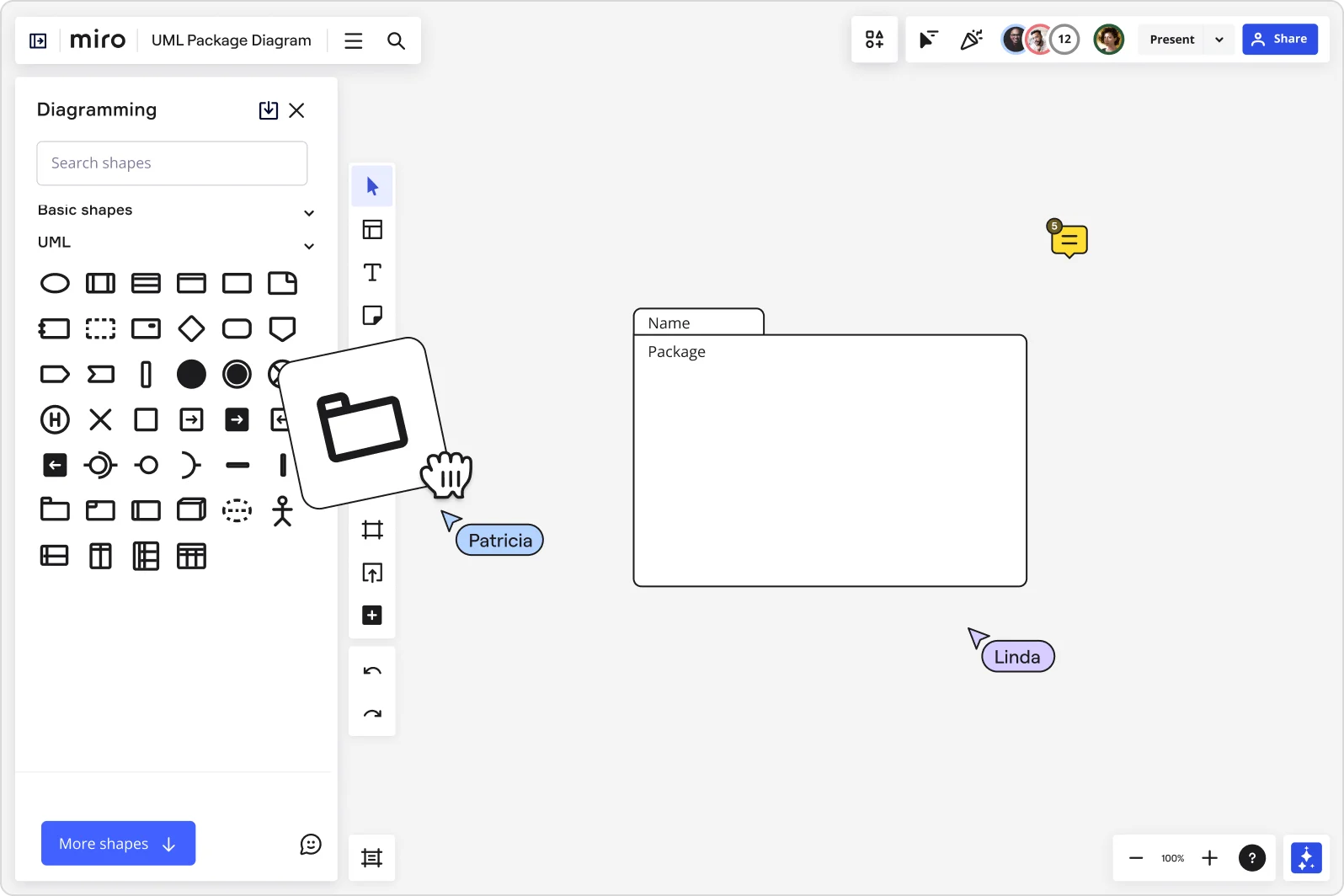
These are the building blocks of a package diagram. Think of a package as a container that holds various UML elements like classes, interfaces, or even other packages. It’s akin to a folder in a file system.
Dependencies
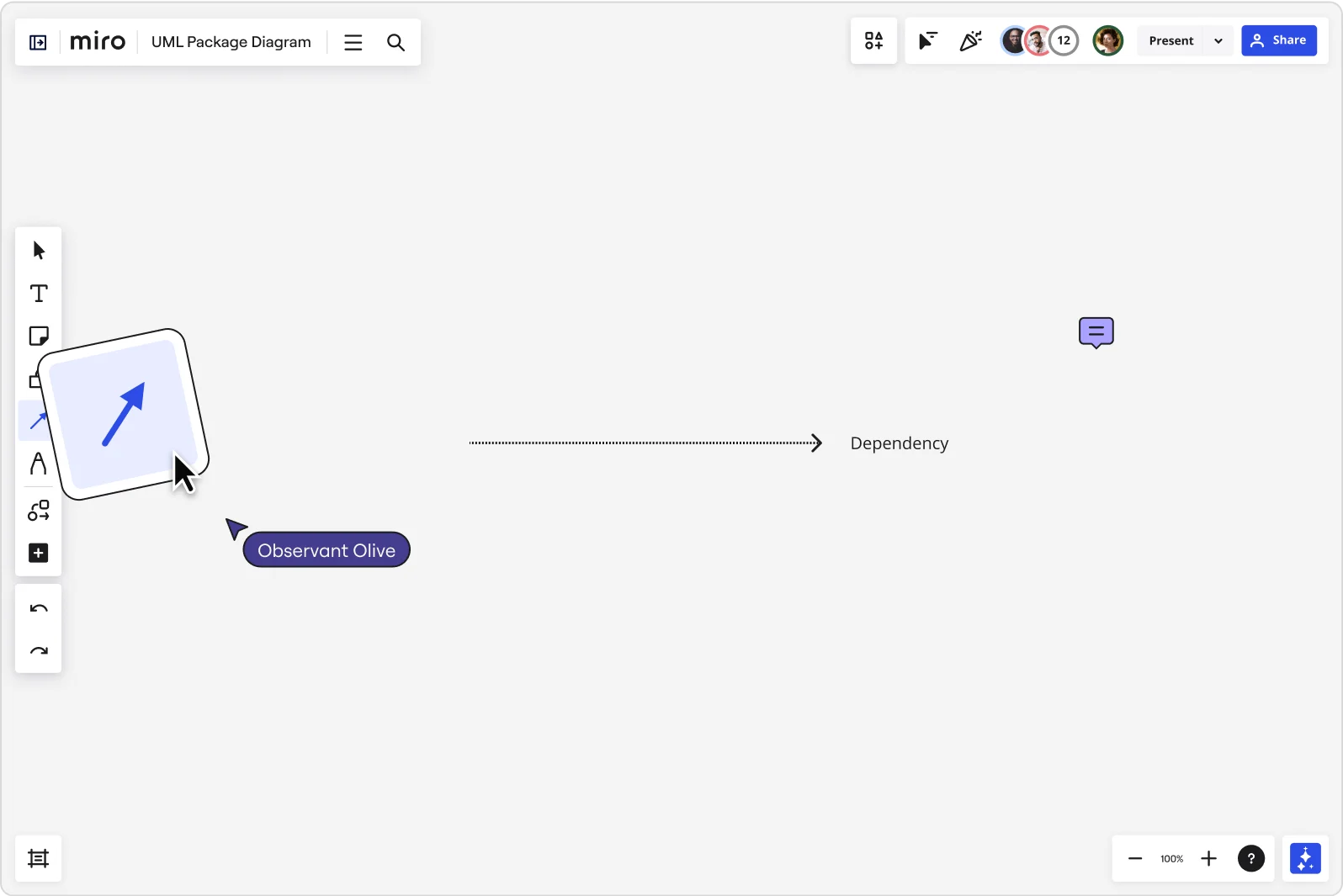
These are the lines that connect packages, illustrating how changes in one package might affect another. They are vital in understanding the interconnected nature of system components.
Relationships
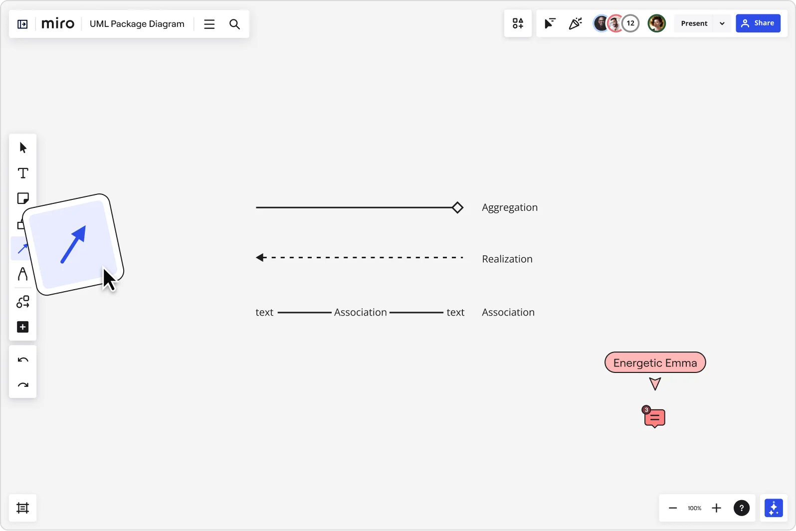
Beyond dependencies, relationships in a package diagram show associations, generalizations, and realizations among packages, offering insights into the system’s hierarchy and structure.
Characteristics of package diagrams
Next, let's examine five characteristics of a package diagram:
1. Package representation
In UML, a package is depicted as a tabbed folder, symbolizing its role as a container for other elements. Each package can contain numerous UML elements, and packages themselves can be nested within other packages, allowing for a hierarchical structure.
2. Dependency indicators
Arrows and lines between packages represent dependencies, indicating how changes in one package might impact others. These dependencies help in understanding the relationships and interactions between different parts of the system.
3. Modularity and encapsulation
Package diagrams promote modularity by allowing developers to group related classes and interfaces together. This encapsulation aids in managing complexity, as changes within a package can often be made independently of others.
4. Scalability and maintainability
By logically organizing the system’s elements, package diagrams make scaling and maintaining the system more manageable. They provide a clear roadmap of the system’s architecture, making it easier to identify where additions or modifications should be made.
5. Communication tool
Beyond their use in design and documentation, package diagrams are excellent tools for communication. They provide a clear and concise way for developers, managers, and even non-technical stakeholders to visualize and discuss the system's structure.
How to draw a package diagram
Creating a package diagram is both an art and a science, demanding clarity and precision. Simply follow these steps:
1. Define the scope of your system
Begin by clearly defining what part of the system your package diagram will represent. This could be the entire system or a specific subsystem. Understanding the scope ensures that your diagram remains focused and relevant.
2. Identify key elements
List out the primary elements within the scope. These could be classes, interfaces, subsystems, or other packages. For those new to UML, think of this as creating an inventory of all the different parts that make up your system.
3. Organize elements into packages
Group related elements into packages. A package should encapsulate elements that functionally belong together. For example, all database-related classes might go into a 'Database' package. It's crucial to ensure these groupings make logical sense and enhance the readability of the diagram.
4. Define package relationships
Determine how these packages interact with each other. Draw dependency lines to illustrate these relationships. Remember, a dependency indicates that a change in one package could affect the other.
5. Refine package contents
Delve into each package, refining its contents. Ensure that each element is in the correct package and that the package itself is necessary. This step might involve breaking down larger packages into smaller, more manageable ones, a process often crucial for advanced users dealing with complex systems.
6. Incorporate additional UML elements
For more advanced diagrams, include elements from other UML diagrams where relevant. This might mean adding notes that reference specific class or activity diagrams, providing a more comprehensive view of the system. This step is completely optional.
7. Review for clarity and accuracy
Examine your diagram for clarity and accuracy. Ensure that it’s not only correct but also easy to understand. This could involve rearranging packages for better flow, adjusting the size of elements for readability, or adding labels for clarity.
8. Validate with stakeholders and iterate as needed
Share the diagram with stakeholders, such as team members, project managers, or clients, for feedback. This step is essential to ensure that the diagram meets the needs of all parties involved and accurately represents the system. Based on the feedback, make necessary adjustments. Package diagrams, like all parts of the software design process, are often iterative. Be prepared to refine your diagram as the system evolves or as you receive more information.
How package diagrams fit into the UML framework
Package diagrams play a significant role in the Unified Modeling Language (UML) framework, a standardized modeling language used in the field of software engineering. UML is designed to provide a consistent way of visualizing the design of a system, and package diagrams contribute to this by offering a unique perspective on the system's structure.
1. Overview of UML framework
The UML framework comprises several types of diagrams, each serving a specific purpose. These include structure diagrams like class diagrams, behavior diagrams like use case and sequence diagrams, and interaction diagrams. Package diagrams fit within the structure diagrams category, focusing on the system’s architecture.
2. Complementary to other diagrams
While other UML diagrams, such as class diagrams, focus on the details of individual classes and their relationships, package diagrams provide a broader view. They help in organizing these classes and interfaces into packages, making it easier to understand the system’s modular structure. This higher-level view complements the more detailed perspectives offered by other diagrams.
3. Facilitating modular design
One of the fundamental principles of software engineering is modular design, and package diagrams are pivotal in achieving this. By grouping related elements, package diagrams help in designing a system that is composed of discrete, reusable modules. This modular approach enhances the maintainability, scalability, and manageability of the system.
4. Managing system complexity
In large software projects, understanding the overall architecture can be challenging. Package diagrams simplify this by providing a clear and organized view of the system's structure. This simplification is crucial for both the development phase and the maintenance phase of a project.
5. Impact on refactoring and scalability
Package diagrams are particularly useful when it comes to refactoring a system or scaling it up with new features. They allow architects and developers to identify which parts of the system are affected by changes and how new components should be integrated into the existing structure.
6. Enhancing communication and documentation
Beyond their technical utility, package diagrams serve as an excellent communication tool. They can be used to convey the system’s architecture to stakeholders, including those who might not have a deep technical background. They also play a vital role in documentation, providing a clear and concise overview of the system’s organization, which is invaluable for both current understanding and future reference.
7. Supporting system analysis and design
Package diagrams are instrumental in the early stages of system analysis and design. They help identify potential modules, envision the system's structure, and plan how different parts of the system will interact. This foresight can lead to more efficient design choices and a more robust final product.
Best practices in package diagram design
Effective package diagram design is a critical skill, balancing detail with readability.
Tips for Effective Visualization: Use color-coding, consistent symbol sizes, and clear labeling to enhance readability. Remember, a well-designed package diagram should communicate its message at a glance.
Ensuring Clarity and Maintainability: Regular updates are crucial for the diagram to remain a true reflection of the system. Adopt practices like version control and documentation to maintain diagram integrity over time.
Tools for crafting package diagrams
Modern tools greatly simplify creating and managing package diagrams. These tools offer features like automatic alignment, easy-to-use interfaces, and collaborative capabilities for team input and review. Miro’s UML diagramming tool is easy to use and has an extensive UML shape pack to suit your needs.
Discover more
What is a UML diagram?
UML component diagrams: A complete guide
UML class diagrams: Definitions, how to make one and more
What is a deployment diagram in UML?
Get on board in seconds
Join thousands of teams using Miro to do their best work yet.

All about UML package diagrams
Why use a uml diagram, i want to create my own use case diagram in lucidchart., i want to create a use case diagram from a lucidchart template..
Use this guide to learn everything you need to know about package diagrams, including what benefits they provide, how to properly build them, and more. With our UML diagram tool, you can take advantage of the structure and organization provided by package diagrams to simplify even the most complicated of UML classifiers.
5 minute read
Do you want to create your own UML diagram? Try Lucidchart. It's fast, easy, and totally free.
What is a package diagram?

Benefits of a package diagram
A well-designed package diagram provides numerous benefits to those looking to create a visualization of their UML system or project.
- They provide a clear view of the hierarchical structure of the various UML elements within a given system.
- These diagrams can simplify complex class diagrams into well-ordered visuals.
- They offer valuable high-level visibility into large-scale projects and systems.
- Package diagrams can be used to visually clarify a wide variety of projects and systems.
- These visuals can be easily updated assystems and projects evolve.
Basic components of a package diagram
The makeup of a package diagram is relatively simple. Each diagram includes only two symbols:
These symbols can be used in a variety of ways to represent different iterations of packages, dependencies, and other elements within a system. Here are the basic components you’ll find within a package diagram:
Packageable element
Dependencies, element import, package import, package merge, dependency notations in a package diagram.
Package diagrams are used, in part, to depict import and access dependencies between packages, classes, components, and other named elements within your system. Each dependency is rendered as a connecting line with an arrow representing the type of relationship between the two or more elements.
There are two main types of dependencies:

Dependencies can also be broken down further into the following categories:
Abstraction
Using packages with other uml diagrams.
As we’ve shown earlier in this guide, packages are UML constructs that can be used to organize the elements within any UML classifier in a variety of UML diagrams. Package diagrams are most commonly found used in:
Use-case diagrams
Class diagrams.
Packages can also be used within other UML model types to organize and arrange elements such as classes, data entities, and use cases. By fuzing the package diagram structure with other UML diagrams, you can simplify any model type, making it easier to understand.
Model diagrams
Package diagrams can also be used in conjunction with model diagrams—a type of UML auxiliary structure diagram used to depict the logical, behavioral, or structural aspects of a system. Even simple models can be difficult to understand without some type of visual organization. The use of packages can provide users with a high-level view of a model with unambiguous named references for each of the elements it contains. In addition, clearly labeled dependencies can clarify the relationships between each element.
Package diagram example
Take a look at the following template to see how a package diagram models the packages within a basic e-commerce web app. Click on the template to modify it and explore how you can show the structure of any designed system at a package level.
- Communication Diagram Tutorial
- How to Draw a Sequence Diagram in UML
- All about composite structure diagrams
- System Sequence Diagrams in UML
- UML Sequence Diagram Tutorial
- State Machine Diagram Tutorial
- All about UML interaction diagrams
- How to Draw an Object Diagram in UML
- How to Draw a Timing Diagram in UML
- How to Draw a Deployment Diagram in UML
- How to Draw a State Machine Diagram in UML
- How to Draw a Communication Diagram in UML
- How to Draw a Component Diagram in UML
- How to Draw a Class Diagram in UML
- Deployment Diagram Tutorial
- Timing Diagram Tutorial
- UML Use Case Diagram Tutorial
- Object Diagram Tutorial
- UML Activity Diagram Tutorial
- What is Unified Modeling Language
- UML Class Diagram Tutorial
- Component Diagram Tutorial
Lucidchart’s innovative and intuitive UML diagram creator helps you generate professional-quality package diagrams that offer clarity to complex systems. Customize one of our many templates from our template gallery or build your diagram from scratch with drag-and-drop shapes to get started.
Try Lucidchart today. It’s quick, easy, and free.

Home » UML » UML Package Diagram: Unveiling the Architecture
UML Package Diagram: Unveiling the Architecture
- Posted on September 13, 2023
- / Under UML
In the realm of software development and system design, understanding and visualizing the architecture of a project is crucial. This is where Unified Modeling Language (UML) comes to the forefront with its array of diagram types, each serving a specific purpose. Among these, the UML Package Diagram stands out as an invaluable tool for depicting the high-level structure of a system or software application. In this article, we will delve into the world of UML Package Diagrams, exploring what they are, how they are used, and why they are essential in software development.
What is a UML Package Diagram?
A UML Package Diagram is a structural diagram that provides a clear and concise representation of the system’s organizational structure. It’s a visual tool used to depict the various packages, sub-packages, and the relationships between them within a system. Think of it as a hierarchical map of your software project, breaking it down into manageable components.
In UML, a package is a general-purpose mechanism to organize elements, such as classes, interfaces, components, and other packages. These packages help in partitioning the system into smaller, more manageable units, allowing for better organization, modularity, and maintenance.
Why Use UML Package Diagrams?
UML Package Diagrams offer several compelling advantages in software development:
- Visualization : They provide a visual representation of the system’s structure, making it easier for developers, architects, and stakeholders to understand the organization of the software.
- Modularity : Packages help in breaking down complex systems into manageable and cohesive modules. This enhances modularity, allowing developers to work on individual packages without affecting the entire system.
- Dependency Management : The arrows representing dependencies between packages assist in identifying relationships and potential bottlenecks in the system. This helps in managing dependencies effectively and avoiding circular dependencies.
- Communication : UML Package Diagrams serve as a powerful communication tool among team members, ensuring everyone is on the same page regarding the system’s architecture.
- Documentation : They provide a visual basis for documenting the system’s structure, which can be invaluable for future maintenance, updates, and knowledge sharing.
Key Elements of a UML Package Diagram
Before we delve deeper into the significance of UML Package Diagrams, let’s explore the key elements that constitute such a diagram:
- Package : The primary element of the diagram, a package, is depicted as a rectangle with a folded-over corner. It represents a container for other elements or sub-packages.
- Package Name : Each package has a name, which is usually placed inside the rectangle.
- Dependencies : Arrows between packages or package contents indicate dependencies between them. These can be used to illustrate which parts of the system rely on others.
- Elements : Inside each package, you can include various elements like classes, interfaces, and other UML diagram elements to represent the components or modules of the system.
- Visibility Symbols : Packages may have visibility symbols (e.g., + for public, – for private) next to their names to denote the access level of their contents.
Package Diagram Example
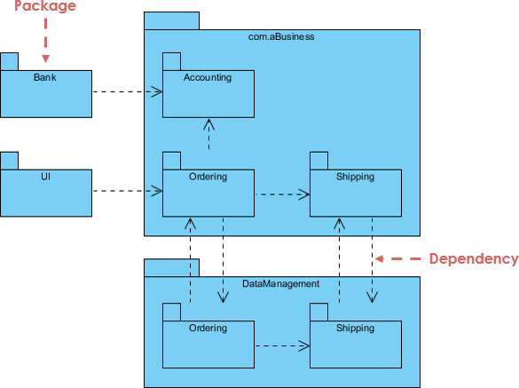
Key Concepts of Package Diagram
In UML Package Diagrams, the emphasis is on organizing and structuring the system’s components into manageable and meaningful packages. These diagrams help software architects and developers to visualize, document, and communicate the architectural aspects of a software system, facilitating better understanding and management of dependencies and modularity.
Let’s break down these concepts and constraints for a clearer understanding:
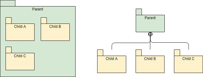
- Hierarchical Structure of Nested Packages : UML Package Diagrams follow a hierarchical structure, where packages can contain other packages, creating a nesting effect. This hierarchical organization helps in structuring and organizing components and modules within a system.
- Atomic Modules for Nested Packages are usually Class Diagrams : In many cases, the atomic modules or elements contained within nested packages are class diagrams. Class diagrams are a common choice to represent the detailed structure of a package’s contents, including classes, interfaces, and their relationships.
- Unique Package Names : Each package within a system should have a unique name. This ensures clarity and avoids ambiguity in identifying different parts of the system.
- Classes with the Same Name : Classes inside different packages can have the same name without conflicts. The package context distinguishes them.
- Variability in Package Content : Packages can vary in terms of what they include. They can contain whole diagrams (such as class diagrams), the names of components (e.g., classes, interfaces), or even no components at all, serving as a purely organizational container.
- Fully Qualified Name of a Package : A fully qualified name of a package is a way to uniquely identify it within the context of the system. The syntax for a fully qualified package name typically follows a hierarchical structure, using dots (.) to separate nested packages. For example, if you have a package structure like “System -> Subsystem -> Component,” the fully qualified name might be “System.Subsystem.Component.”
- Representation of Packages : Packages in UML Package Diagrams can be represented using notations that visually depict them. These notations often involve rectangular shapes with tabs at the top to display the package name. Additionally, dependencies between packages can be represented using arrows, typically with dotted lines, to illustrate how one package depends on another.
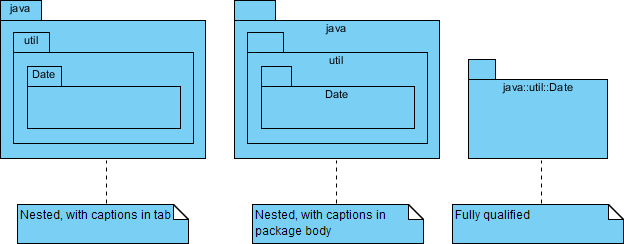
Representing Dependencies between Packages
Overall, UML Package Diagrams play a crucial role in software architecture by providing a high-level view of the organization and dependencies between packages, which is essential for effective system design, communication, and documentation.
For example, the use of stereotypes like <<import>> and <<access>> adds clarity and specificity to the types of dependencies being depicted, enhancing the diagram’s comprehensibility.
Let’s expand on these concepts:
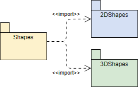
- Meaning : In UML Package Diagrams, a <<import>> dependency signifies that one package imports the functionality or elements of another package. This allows the importing package to use or access elements from the imported package without necessarily including them physically.
- Representation : This dependency can be represented using the <<import>> stereotype, typically displayed above the dependency arrow between the two packages involved.

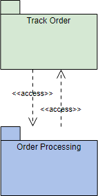
- Meaning : The <<access>> dependency indicates that one package requires the assistance or services provided by the functions or elements of another package. It implies a runtime or execution-level dependency between the two packages.
- Representation : Similar to <<import>>, the <<access>> dependency can be represented with the <<access>> stereotype placed above the dependency arrow between the packages.

- While <<import>> and <<access>> are commonly used stereotypes to represent dependencies in package diagrams, UML allows users to define their own custom stereotypes to represent specific types of dependencies. This flexibility allows you to tailor your diagrams to accurately depict the relationships between packages in your system.
Modeling Complex Grouping :
- Package diagrams are indeed ideal for modeling complex grouping and hierarchical relationships between packages and other objects in a system. They help to create a visual representation of the organization and structure of a software system, making it easier for stakeholders to understand how components are grouped and how they interact.
How to Create a UML Package Diagram
Creating a UML Package Diagram involves the following steps:
- Identify Packages : Determine the main packages and sub-packages in your system. Think about how you want to organize your components logically.
- Define Relationships : Establish dependencies between packages using arrows. Use solid lines for strong dependencies and dashed lines for weaker ones.
- Add Elements : Populate the packages with classes, interfaces, or other relevant UML elements. Connect these elements to the packages to illustrate their membership.
- Include Visibility Symbols : If necessary, add visibility symbols to denote the access level of package contents.
- Label Packages : Label each package with a meaningful name that reflects its purpose within the system.
- Review and Refine : Review the diagram for accuracy and clarity. Refine it as needed to ensure it effectively communicates the system’s architecture.
UML Package Diagrams are a vital tool for understanding, documenting, and communicating the architecture of software systems. They enable developers and architects to break down complex systems into manageable packages, visualize dependencies, and ensure clear communication among team members. By utilizing UML Package Diagrams, software projects can benefit from improved organization, modularity, and maintainability, ultimately leading to more successful and efficient development processes. So, the next time you embark on a software development journey, consider unveiling the architecture with the power of UML Package Diagrams.
Leave a Comment Cancel reply
Your email address will not be published. Required fields are marked *
Save my name, email, and website in this browser for the next time I comment.

- Visual Paradigm Online
- Request Help
- Customer Service
- Community Circle
- Demo Videos
- Visual Paradigm
- YouTube Channel
- Academic Partnership

Home » IT » What is a Package? What is a Package Diagram in UML?
What is a Package? What is a Package Diagram in UML?
- Posted on February 9, 2022
- / With 8 Comments
What is A Package?
Packages in the Unified Modeling Language are used to group elements and provide namespaces for the grouped elements. A package can contain other packages, thus providing a hierarchical organization of packages.
Almost all UML elements can be grouped into packages. Thus, classes, objects, use cases, components, nodes, node instances, etc. can be organized into packages, thus making the organization of the myriad elements contained in a real-world UML model manageable.
In this example, there is a package containing a class diagram.
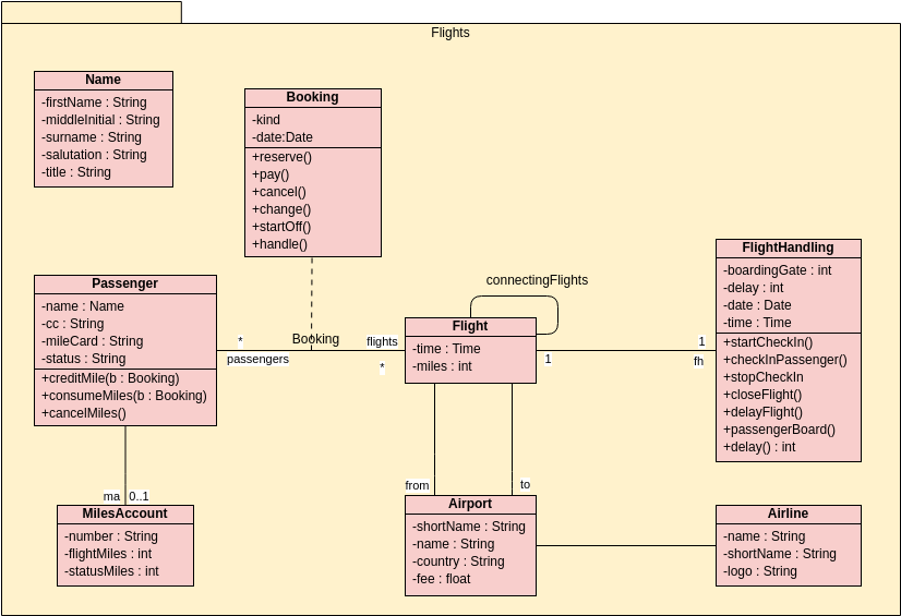
What is a Package Diagram in UML?
Large systems provide special challenges. Drawing a model of a class for a large system is too big for it to understand. There are too many connections between classes to understand. A useful technique for dealing with this problem is the UML package. Packages in the Unified Modeling Language help.
- To group elements
- To provide a namespace for the grouped elements
- A package may contain other packages, thus providing for a hierarchical organization of packages.
- UML elements can be grouped into packages.
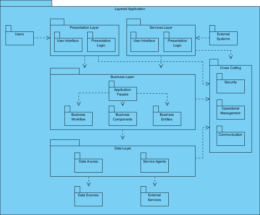
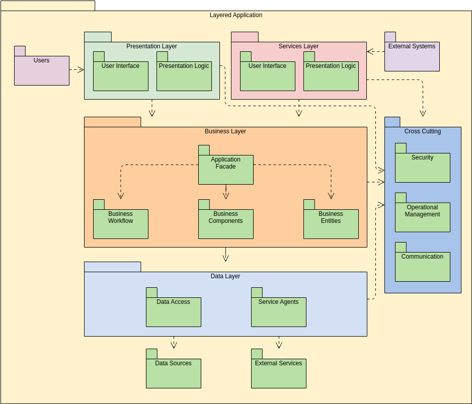
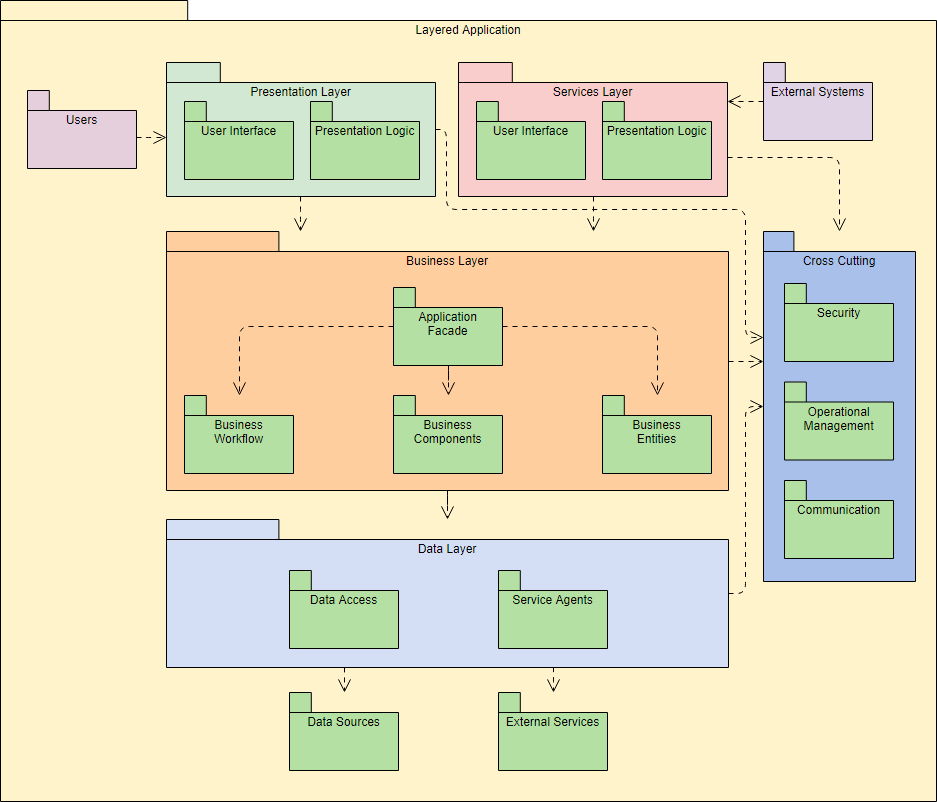
Thus, a package diagram, a structure diagram, shows the arrangement and organization of model elements in a medium to large project. Package diagrams can show both the structure and the dependencies between subsystems or modules, showing different views of a system, for example, as a multi-layer (aka multilayer) application – a multi-layer application model.
Package Diagram Examples
Package diagram shows the arrangement and organization of model elements in middle to large scale project that can be used to show both structure and dependencies between sub-systems or modules.
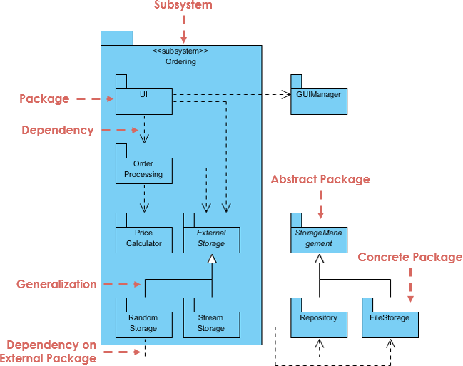
More UML Package Diagram Examples
Layered Application
- What’s New
- Infographics
- Terms of Service
- Privacy Policy
- Security Overview
- Report Abuse
- UML Tutorial
- Book a Demo
- UML 2 Tutorial
- Package Diagram
UML 2 Tutorial - Package Diagram
Package diagrams.
Package diagrams are used to reflect the organization of packages and their elements. When used to represent class elements, package diagrams provide a visualization of the namespaces. The most common use for package diagrams is to organize use case diagrams and class diagrams, although the use of package diagrams is not limited to these UML elements. The following is an example of a package diagram.
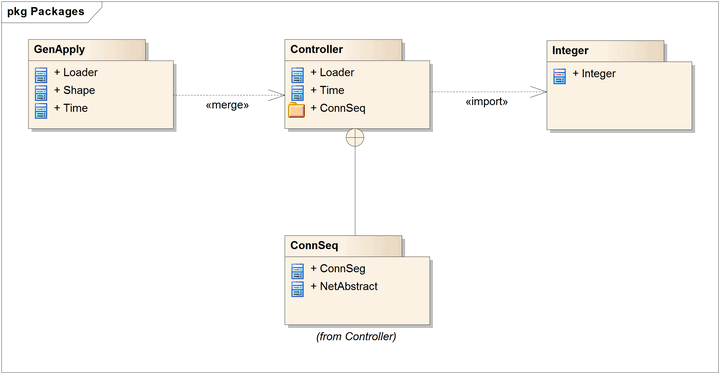
Elements contained in a package share the same namespace. Therefore, the elements contained in a specific namespace must have unique names.
Packages can be built to represent either physical or logical relationships. When choosing to include classes in specific packages, it is useful to assign the classes with the same inheritance hierarchy to the same package. There is also a strong argument for including classes that are related via composition, and classes that collaborate with them, in the same package.
Packages are represented in UML 2.1 as folders and contain the elements that share a namespace; all elements within a package must be identifiable, and so have a unique name or type. The package must show the package name and can optionally show the elements within the package in extra compartments.
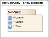
Package Merge
A «merge» connector between two packages defines an implicit generalization between elements in the source package, and elements with the same name in the target package. The source element definitions are expanded to include the element definitions contained in the target. The target element definitions are unaffected, as are the definitions of source package elements that don't match names with any element in the target package.
Package Import
The «import» connector indicates that the elements within the target package, which in this example is a single class, use unqualified names when being referred to from the source package. The source package's namespace gains access to the target classes; the target's namespace is not affected.
Nesting Connectors
The nesting connector between the target package and source packages shows that the source package is fully contained in the target package.
- Enterprise Architect
- Pro Cloud Server
- Prolaborate
- UML at a Glance
- PHP UML Modeling
- Business Process Modeling
- Model Driven Architecture
- Requirements Management
- Software Development
- Small/Medium Enterprise
- IT Professionals
- UML 2.0 Tutorial
- Corporate Resources
- Developer Resources
- Media Resources
- Online Manual
- Report a Bug
- Feature Request
- Compare Editions
- System Requirements
- Global Partners
- Sister Companies
- Technical Partners
- Standards Organizations
UML Package Diagrams Notation
Package diagram is UML structure diagram which shows packages and dependencies between the packages.
Model diagrams allow to show different views of a system, for example, as multi-layered (aka multi-tiered) application - multi-layered application model .
The following nodes and edges are typically drawn in a package diagram: package , packageable element , dependency , element import , package import , package merge .
Package is a namespace used to group together elements that are semantically related and might change together. It is a general purpose mechanism to organize elements into groups to provide better structure for system model.
Owned members of a package should all be packageable elements . If a package is removed from a model, so are all the elements owned by the package. Package by itself is packageable element , so any package could be also a member of other packages.
Because package is a namespace, elements of related or the same type should have unique names within the enclosing package. Different types of elements are allowed to have the same name.
As a namespace , a package can import either individual members of other packages or all the members of other packages. Package can also be merged with other packages.
A package is rendered as a tabbed folder - a rectangle with a small tab attached to the left side of the top of the rectangle. If the members of the package are not shown inside the package rectangle, then the name of the package should be placed inside.

Package org.hibernate
The members of the package may be shown within the boundaries of the package. In this case the name of the package should be placed on the tab.
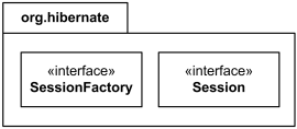
Package org.hibernate contains SessionFactory and Session
A diagram showing a package with content is allowed to show only a subset of the contained elements according to some criterion.
Members of the package may be shown outside of the package by branching lines from the package to the members. A plus sign (+) within a circle is drawn at the end attached to the namespace (package). This notation for packages is semantically equivalent to composition (which is shown using solid diamond.)
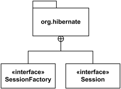
Package org.hibernate contains interfaces SessionFactory and Session.
The elements that can be referred to within a package using non-qualified names are:
- owned elements,
- imported elements, and
- elements in enclosing (outer) namespaces.
Owned and imported elements may have a visibility that determines whether they are available outside the package.
If an element that is owned by a package has visibility, it could be only public or private visibility. Protected or package visibility is not allowed. The visibility of a package element may be indicated by preceding the name of the element by a visibility symbol ("+" for public and "-" for private).
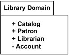
All elements of Library Domain package are public except for Account
The public elements of a package are always accessible outside the package through the use of qualified names.
Package URI Attribute
Package has optional URI attribute which serves as unique identifier of the package. This attribute was introduced in UML 2.4 mostly to support exchange of profiles using XMI.
Note, that UML 2.4 specification requires this URI attribute to follow the rules and syntax of the IETF URI specification RFC 2396 while the more recent version of the URI syntax RFC 3986 (released in 2005) rendered the RFC 2396 obsolete.
Both RFCs allow URIs to be uniform resource locators (URLs), uniform resource names (URNs) or both. Though URN actually defines item's identity (unique id) and URL provides a method for finding it, it is very common and sometimes confusing to see URLs serving as URNs.
Here's some examples of package URI attribute in the form of URL . Note, that using "http://" scheme is often not related to HTTP protocol and no actual resource is located at that location. URL is just used as a substitute of unique id:
- http://www.ietf.org/rfc/rfc2396.txt
- http://www.omg.org/spec/UML/20100901/PrimitiveTypes.xmi
- http://www.uml-diagrams.org/profiles/20110410/EJB-30.xmi
My personal preference is to use URNs instead, as URN was designed specifically to define identity (unique id) and does not imply availability of the identified resource (e.g. for obsolete resources):
- urn:ietf:rfc:3986
- urn:oasis:names:specification:docbook:dtd:xml:4.1.2
- urn:schemas-microsoft-com:xml-data
- urn:uml-diagrams-org:profiles:20110410:EJB-30
The URI attribute of a package may be rendered in the form {uri=<uri>} after the package name.
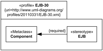
EJB Profile shown as a package with URI attribute.
Package Template
Package can be used as a template for other packages. Note, that [UML 2.4.1 Specification] inconsistently calls it both package template and template package .
Packageable element can be used as a template parameter . A package template parameter may refer to any element owned or used by the package template, or templates nested within it.
A package may be bound to one or more template packages. When several bindings are applied the result of bindings is produced by taking the intermediate results and merging them into the combined result using package merge .
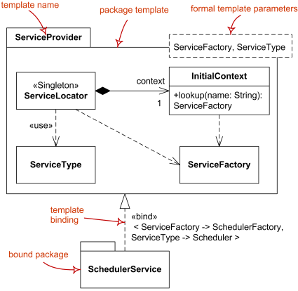
Package template Service Provider and bound package Scheduler Service.
Packageable Element
Some examples of packageable elements are:
- Classifier (--> Type)
- Class (--> Classifier)
- Use Case (--> Classifier)
- Component (--> Classifier)
Packageable element by itself has no notation, see specific subclasses.
What is a Package Diagram in UML?
Nested and hierarchical packages.
- When to Draw Package Diagram?
Criteria for Decomposing a System into Packages
- How to Create Package Diagram?
Package Diagram Examples
Package diagram tutorial.
Package diagram shows the arrangement and organization of model elements in middle to large scale project that can be used to show both structure and dependencies between sub-systems or modules.
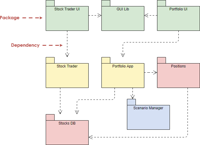
Big systems offer special challenges. Draw a class model for a large system, and it is too big to comprehend. There are too many links between classes to understand. A useful technique to handle this is that of UML's packages. A package in the Unified Modeling Language helps:
- To group elements
- To provide a namespace for the grouped elements
- A package may contain other packages, thus providing for a hierarchical organization of packages.
- UML elements can be grouped into packages.
The illustration below shows an example package diagram is used to represent the composition of a business.

Finding an online Package Diagram tool? Just click the draw button on the right to create your Package Diagram online. Visual Paradigm Online is free * and intuitive. You can also go through this Package Diagram tutorial to learn about Package Diagram before you get started.
Package Diagram Notations
Package diagrams are used to structure high level systems. Packages are used for organizing large system which contains diagrams, documents and other key deliverables. In other words, packages can be used as a part of other diagrams also.
A package can be represented as a hierarchical structure with nested packages. Atomic module for nested package are usually class diagrams.
The figure below gives an example of package diagram that consists of several nested packages.
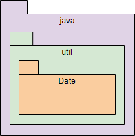
There are few constraints while using package diagrams, they are as follows.
- The name of packages should be unique within a system. However, it is allowed for classes inside different packages to have same name. For Example, Package::Product & Shipping::Product are allowed.
- Users should avoid using package name delivered by the programming language. For Example, Java provides Date as a package. So, programmers should construct package with name Date.
- Packages can include whole diagrams, name of components alone or no components at all.
A package can also has a fully qualified name. The figure below shows an example use of such a package.
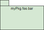
- UML, C++, Perl, Ruby myPkg::foo::bar
- Java, C# myPkg.foo.bar
Package Containment
- Packages are shown in static diagrams
There are two sub-types involved in dependency. They are <<access>> & <<import>>. Though there are two stereotypes users can use their own stereotype to represent the type of dependency between two packages.
<<import>> - one package imports the functionality of other package

Example – <<import>> Dependency
<<access>> - one package requires help from functions of other package

When to draw Package Diagram?
The UML does not treat package diagrams as a separate technique, It is often useful to combine them by grouping other model elements together into different packages on the same diagram. Package diagrams can be useful in many ways, such as:
- To create an overview of a large set of model elements
- To organize a large model
- To group related elements
- To separate namespaces
- Different owners - who is responsible for working on which diagrams?
- Different applications - each problem has its own obvious partitions;
- Clusters of classes with strong cohesion - e.g., course, course description, instructor, student,...
- Or: use an architectural pattern to help find a suitable decomposition such as MVC Framework
Other Guidelines for Packages
- Gather model elements with strong cohesion in one package
- Keep model elements with low coupling in different packages
- Minimize relationships, especially associations, between model elements in different packages
- Namespace implication: an element imported into a package does not "know" how it is used in the imported package
How to Create a Package Diagram?
The following example shows the Track Order Service for an online shopping store.
Track Order Service is responsible for providing tracking information for the products ordered by customers. Customer types in the tracking serial number, Track Order Service refers the system and updates the current shipping status to the customer.
Step 1 - Identify the packages present in the system
- There is a "track order" service, it has to talk with other module to know about the order details, let us call it "Order Processing" .
- Next after fetching Order Details it has to know about shipping details, let us call that as "Shipping" .
- Finally if knows the status of the order it has to update the information to the user, let us call this module as "UI Framework" .

Step 2 - Identify the dependencies
Package Diagram Example – MVC Structure
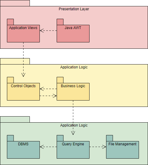
Package Diagram Example - Layering Structure
Want to draw a Package Diagram?
You've learned what a Package Diagram is and how to draw a Package Diagram step-by-step. It's time to get your hands dirty by drawing a Package Diagram of your own. Draw UML diagrams free * with Visual Paradigm Online. It's easy-to-use, intuitive.
* The Free edition supports free usage of Visual Paradigm Online for non-commercial use only.
©2024 by Visual Paradigm. All rights reserved.
- Terms of Service
- Privacy Policy
- Security Overview
Package Diagram: Definition, Components, and Examples
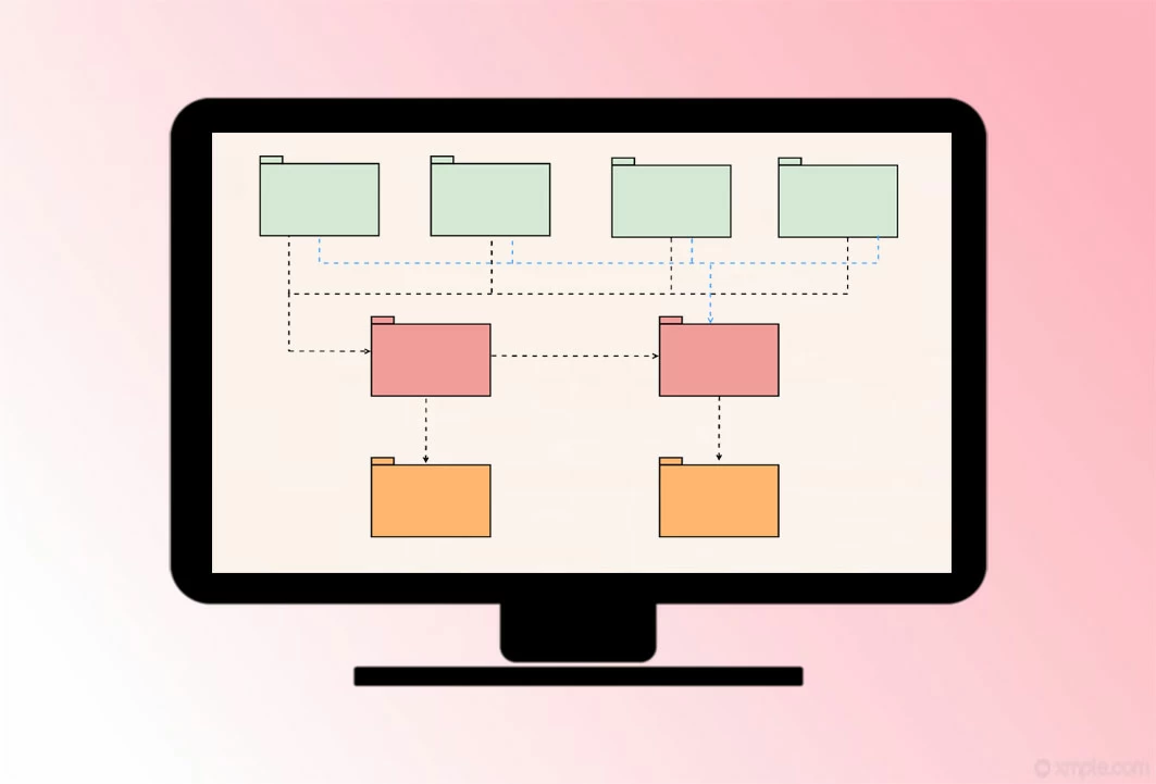
Application Scenarios of Package Diagram
Basic components of package diagram.
- How to Draw Package Diagram in GitMind
What is Package Diagram in UML?
Package diagrams are structural diagram which is commonly used to simplify complex class diagrams and organize classes into packages. A package is a collection of related UML elements including diagrams, documents, classes, and event packages. Aside from that, the package diagram offers valuable high-level visibility for large projects and systems. To better understand how to create a package diagram, continue reading this article as we discuss further below.
A package diagram commonly used to organize the high-level system elements so that the packages can be used for large system organization which contains documents, diagrams, and others. In fact, we listed some tips below where do you use the package diagram.
- A package diagram can be used to simplify complex class diagrams and arrange the classes into packages.
- It can also be used to define the groupings amongst packages and other packages or objects.
- It can complex structure in technology, education, and other related fields into simplified packages.
If you want to draw this package diagram, you just need to be familiarized with the components that this diagram has. These are few basic shapes, symbols, and components, they are as follows.
- Rectangle – the TAB appears in the rectangle and the package appears at the top of the rectangle with small labels. This group common elements based on user interaction, data, and behavior.
- Dashed arrows – this symbol indicates the dependencies wherein it is a visual representation of how elements influence another.
- Interface – this is the specification of the pattern.
- Object – this symbol is an instance of a class. Moreover, it is commonly used to represent an item.
- Package – this is a namespace used to group related elements within a system.
- Packageable Element – it can be rendered as a rectangle that can be labeled with a suitable name. This includes events, components, use cases, and packages.
- Dependencies – This is a representation of how elements influence another.
- Element Import – This is used to import individual elements without resorting to a package import.
- Package Import – this is a directed relationship that adds the names of the members of the imported package.
- Package Merge – this is a directed relationship wherein the contents of one package are extended by another content.
How to Draw Package Diagram in GitMind?
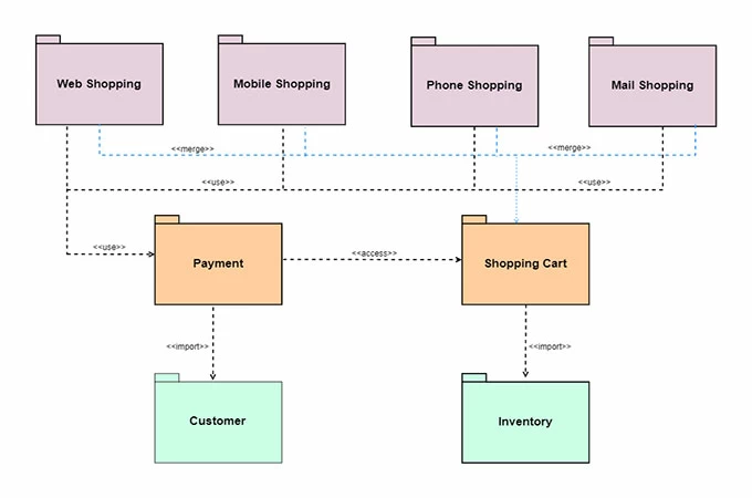
Now that you have an idea of how to draw a UML package diagram using the basic shapes and symbols. It’s now the time to try it on your own and apply the things that you’ve learned by using GitMind . This is a free online mind mapping tool that is perfectly made for project planning, concept mapping, and other creative tasks. Moreover, you can easily create a diagram since it has a simple and clean interface. Aside from that, it offers editable stylish templates that can be used by all users. What’s more, See the full guide below to show how to make a package diagram example.
- On your computer, go to your favorite browser and visit the GitMind official page by typing it on the search bar.
- Once you are on the page, click the “Get Started” button and you will be directed to the editable templates. Hit the “New Flowchart” button then under the “UML Class Diagram” and click the rectangle for the package diagram and start making and customizing your ideas and thoughts using the shapes and other symbols on the flowchart editor.
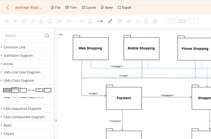
- When you are done, save the diagram by clicking the “Save” button.
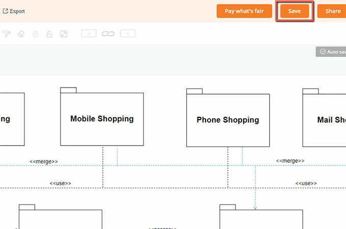
Or you can draw package diagram using the tool’s desktop version which you can download from the button below.
Using a package diagram, you will be able to organize or arrange large models, group-related elements, and separate namespaces. Although you are a beginner or a pro, you can create your own package diagram using this basic information and symbols with the help of GitMind.
Related posts:
- Top 10 Free Flowchart Maker for Windows and Mac
- Top 10 Free Family Tree Makers in 2024

Leave a Comment
Comment (0).
This website uses cookies that are essential for the operations of this website and its core functions. Other cookies will only be placed with your consent. For more details visit our Cookies Policy .
- System Design Tutorial
- What is System Design
- System Design Life Cycle
- High Level Design HLD
- Low Level Design LLD
- Design Patterns
- UML Diagrams
- System Design Interview Guide
- Crack System Design Round
- System Design Bootcamp
- System Design Interview Questions
- Microservices
- Scalability
- What is High Level Design – Learn System Design
- Horizontal and Vertical Scaling | System Design
- Availability in System Design
- Consistency in System Design
- Reliability in System Design
- CAP Theorem in System Design
- Difference between Concurrency and Parallelism
- What is Load Balancer & How Load Balancing works?
- What is Content Delivery Network(CDN) in System Design
- Caching - System Design Concept
- Message Queues | System Design
- Communication Protocols In System Design
- Network Protocols and Proxies in System Design
Unified Modeling Language (UML) Diagrams
Unified Modeling Language (UML) is a general-purpose modeling language. The main aim of UML is to define a standard way to visualize the way a system has been designed. It is quite similar to blueprints used in other fields of engineering. UML is not a programming language , it is rather a visual language.
- We use UML diagrams to portray the behavior and structure of a system.
- UML helps software engineers, businessmen, and system architects with modeling, design, and analysis.
- The Object Management Group (OMG) adopted Unified Modelling Language as a standard in 1997. It’s been managed by OMG ever since.
- The International Organization for Standardization (ISO) published UML as an approved standard in 2005. UML has been revised over the years and is reviewed periodically.

Important Topics for the UML Diagrams
- Why do we need UML?
- Different Types of UML Diagrams
- Structural UML Diagrams
- Behavioral UML Diagrams
- Object-Oriented Concepts Used in UML Diagrams
- Tools for creating UML Diagrams
- Steps to create UML Diagrams
- UML diagrams best practices
- UML and Agile Development
- Common Challenges in UML Modeling:
1. Why do we need UML?
- Complex applications need collaboration and planning from multiple teams and hence require a clear and concise way to communicate amongst them.
- Businessmen do not understand code. So UML becomes essential to communicate with non-programmers about essential requirements, functionalities, and processes of the system.
- A lot of time is saved down the line when teams can visualize processes, user interactions, and the static structure of the system.
2. Different Types of UML Diagrams
UML is linked with object-oriented design and analysis. UML makes use of elements and forms associations between them to form diagrams. Diagrams in UML can be broadly classified as:

3. Structural UML Diagrams
3.1. class diagram.
The most widely use UML diagram is the class diagram. It is the building block of all object oriented software systems. We use class diagrams to depict the static structure of a system by showing system’s classes, their methods and attributes. Class diagrams also help us identify relationship between different classes or objects.
3.2. Composite Structure Diagram
We use composite structure diagrams to represent the internal structure of a class and its interaction points with other parts of the system.
- A composite structure diagram represents relationship between parts and their configuration which determine how the classifier (class, a component, or a deployment node) behaves.
- They represent internal structure of a structured classifier making the use of parts, ports, and connectors.
- We can also model collaborations using composite structure diagrams.
- They are similar to class diagrams except they represent individual parts in detail as compared to the entire class.
3.3. Object Diagram
An Object Diagram can be referred to as a screenshot of the instances in a system and the relationship that exists between them. Since object diagrams depict behaviour when objects have been instantiated, we are able to study the behaviour of the system at a particular instant.
- An object diagram is similar to a class diagram except it shows the instances of classes in the system.
- We depict actual classifiers and their relationships making the use of class diagrams.
- On the other hand, an Object Diagram represents specific instances of classes and relationships between them at a point of time.
3.4. Component Diagram
Component diagrams are used to represent how the physical components in a system have been organized. We use them for modelling implementation details.
- Component Diagrams depict the structural relationship between software system elements and help us in understanding if functional requirements have been covered by planned development.
- Component Diagrams become essential to use when we design and build complex systems.
- Interfaces are used by components of the system to communicate with each other.
3.5. Deployment Diagram
Deployment Diagrams are used to represent system hardware and its software.It tells us what hardware components exist and what software components run on them.
- We illustrate system architecture as distribution of software artifacts over distributed targets.
- An artifact is the information that is generated by system software.
- They are primarily used when a software is being used, distributed or deployed over multiple machines with different configurations.
3.6. Package Diagram
We use Package Diagrams to depict how packages and their elements have been organized. A package diagram simply shows us the dependencies between different packages and internal composition of packages.
- Packages help us to organise UML diagrams into meaningful groups and make the diagram easy to understand.
- They are primarily used to organise class and use case diagrams.
4. Behavioral UML Diagrams
4.1. state machine diagrams.
A state diagram is used to represent the condition of the system or part of the system at finite instances of time. It’s a behavioral diagram and it represents the behavior using finite state transitions.
- State diagrams are also referred to as State machines and State-chart Diagrams
- These terms are often used interchangeably. So simply, a state diagram is used to model the dynamic behavior of a class in response to time and changing external stimuli.
4.2. Activity Diagrams
We use Activity Diagrams to illustrate the flow of control in a system. We can also use an activity diagram to refer to the steps involved in the execution of a use case.
- We model sequential and concurrent activities using activity diagrams. So, we basically depict workflows visually using an activity diagram.
- An activity diagram focuses on condition of flow and the sequence in which it happens.
- We describe or depict what causes a particular event using an activity diagram.
4.3. Use Case Diagrams
Use Case Diagrams are used to depict the functionality of a system or a part of a system. They are widely used to illustrate the functional requirements of the system and its interaction with external agents(actors).
- A use case is basically a diagram representing different scenarios where the system can be used.
- A use case diagram gives us a high level view of what the system or a part of the system does without going into implementation details.
4.4. Sequence Diagram
A sequence diagram simply depicts interaction between objects in a sequential order i.e. the order in which these interactions take place.
- We can also use the terms event diagrams or event scenarios to refer to a sequence diagram.
- Sequence diagrams describe how and in what order the objects in a system function.
- These diagrams are widely used by businessmen and software developers to document and understand requirements for new and existing systems.
4.5. Communication Diagram
A Communication Diagram (known as Collaboration Diagram in UML 1.x) is used to show sequenced messages exchanged between objects.
- A communication diagram focuses primarily on objects and their relationships.
- We can represent similar information using Sequence diagrams, however communication diagrams represent objects and links in a free form.
4.6. Timing Diagram
Timing Diagram are a special form of Sequence diagrams which are used to depict the behavior of objects over a time frame. We use them to show time and duration constraints which govern changes in states and behavior of objects.
4.7. Interaction Overview Diagram
An Interaction Overview Diagram models a sequence of actions and helps us simplify complex interactions into simpler occurrences. It is a mixture of activity and sequence diagrams.
5. Object-Oriented Concepts Used in UML Diagrams
- Class: A class defines the blue print i.e. structure and functions of an object.
- Objects : Objects help us to decompose large systems and help us to modularize our system. Modularity helps to divide our system into understandable components so that we can build our system piece by piece.
- Inheritance: Inheritance is a mechanism by which child classes inherit the properties of their parent classes.
- Abstraction: Abstraction in UML refers to the process of emphasizing the essential aspects of a system or object while disregarding irrelevant details. By abstracting away unnecessary complexities, abstraction facilitates a clearer understanding and communication among stakeholders.
- Encapsulation: Binding data together and protecting it from the outer world is referred to as encapsulation.
- Polymorphism: Mechanism by which functions or entities are able to exist in different forms.
5.1. Additions in UML 2.0
- Software development methodologies like agile have been incorporated and scope of original UML specification has been broadened.
- Originally UML specified 9 diagrams. UML 2.x has increased the number of diagrams from 9 to 13. The four diagrams that were added are : timing diagram, communication diagram, interaction overview diagram and composite structure diagram. UML 2.x renamed statechart diagrams to state machine diagrams.
- UML 2.x added the ability to decompose software system into components and sub-components.
6. Tools for creating UML Diagrams
There are several tools available for creating Unified Modeling Language (UML) diagrams, which are commonly used in software development to visually represent system architecture, design, and implementation. Here are some popular UML diagram creating tools:
- Lucidchart: Lucidchart is a web-based diagramming tool that supports UML diagrams. It’s user-friendly and collaborative, allowing multiple users to work on diagrams in real-time.
- Draw.io: Draw.io is a free, web-based diagramming tool that supports various diagram types, including UML. It integrates with various cloud storage services and can be used offline.
- Visual Paradigm: Visual Paradigm provides a comprehensive suite of tools for software development, including UML diagramming. It offers both online and desktop versions and supports a wide range of UML diagrams.
- StarUML: StarUML is an open-source UML modeling tool with a user-friendly interface. It supports the standard UML 2.x diagrams and allows users to customize and extend its functionality through plugins.
- Papyrus: Papyrus is an open-source UML modeling tool that is part of the Eclipse Modeling Project. It provides a customizable environment for creating, editing, and visualizing UML diagrams.
- PlantUML: PlantUML is a text-based tool that allows you to create UML diagrams using a simple and human-readable syntax. It’s often used in conjunction with other tools and supports a variety of diagram types.
7. Steps to create UML Diagrams

Creating Unified Modeling Language (UML) diagrams involves a systematic process that typically includes the following steps:
- Determine the purpose of creating the UML diagram. Different types of UML diagrams serve various purposes, such as capturing requirements, designing system architecture, or documenting class relationships.
- Identify the key elements (classes, objects, use cases, etc.) and their relationships that need to be represented in the diagram. This step involves understanding the structure and behavior of the system you are modeling.
- Choose the UML diagram type that best fits your modeling needs. Common types include Class Diagrams, Use Case Diagrams, Sequence Diagrams, Activity Diagrams, and more.
- Before using a UML modeling tool, it can be helpful to create a rough sketch on paper or a whiteboard. This can help you visualize the layout and connections between elements.
- Select a UML modeling tool that suits your preferences and requirements. There are various tools available, both online and offline, that offer features for creating and editing UML diagrams.
- Open the selected UML modeling tool and create a new project or diagram. Begin adding elements (e.g., classes, use cases, actors) to the diagram and connect them with appropriate relationships (e.g., associations, dependencies).
- For each element in the diagram, specify relevant properties and attributes. This might include class attributes and methods, use case details, or any other information specific to the diagram type.
- Enhance the clarity of your diagram by adding annotations, comments, and explanatory notes. This helps anyone reviewing the diagram to understand the design decisions and logic behind it.
- Review the diagram for accuracy and completeness. Ensure that the relationships, constraints, and elements accurately represent the intended system or process. Validate your diagram against the requirements and make necessary adjustments.
- Refine the diagram based on feedback and additional insights. UML diagrams are often created iteratively as the understanding of the system evolves.
- Some UML tools allow you to generate documentation directly from your diagrams. This can include class documentation, use case descriptions, and other relevant information.
Note: Remember that the specific steps may vary based on the UML diagram type and the tool you are using.
8. UML diagrams best practices
Unified Modeling Language (UML) is a powerful tool for visualizing and documenting the design of a system. To create effective and meaningful UML diagrams, it’s essential to follow best practices. Here are some UML best practices:
- Understand the Audience: Consider your audience when creating UML diagrams. Tailor the level of detail and the choice of diagrams to match the understanding and needs of your audience, whether they are developers, architects, or stakeholders.
- Keep Diagrams Simple and Focused: Aim for simplicity in your diagrams. Each diagram should focus on a specific aspect of the system or a particular set of relationships. Avoid clutter and unnecessary details that can distract from the main message.
- Use Consistent Naming Conventions: Adopt consistent and meaningful names for classes, objects, attributes, methods, and other UML elements. Clear and well-thought-out naming conventions enhance the understandability of your diagrams.
- Follow Standard UML Notations: Adhere to standard UML notations and symbols. Consistency in using UML conventions ensures that your diagrams are easily understood by others who are familiar with UML.
- Keep Relationships Explicit: Clearly define and label relationships between elements. Use appropriate arrows, multiplicity notations, and association names to communicate the nature of connections between classes, objects, or use cases.
9. UML and Agile Development
Unified Modeling Language (UML) and Agile development are two different approaches to software development, and they can be effectively integrated to enhance the overall development process. Here are some key points about the relationship between UML and Agile development:
9.1. UML in Agile Development
- Visualization and Communication: UML diagrams provide a visual way to represent system architecture, design, and behavior. In Agile development, where communication is crucial, UML diagrams can serve as effective communication tools between team members, stakeholders, and even non-technical audiences.
- User Stories and Use Cases: UML use case diagrams can be used to capture and model user stories in Agile development. Use cases help in understanding the system from an end-user perspective and contribute to the creation of user stories.
- Iterative Modeling: Agile methodologies emphasize iterative development, and UML can be adapted to support this approach. UML models can be created and refined incrementally as the understanding of the system evolves during each iteration.
- Agile Modeling Techniques: Agile modeling techniques, such as user story mapping and impact mapping, complement UML by providing lightweight ways to visualize and communicate requirements and design. These techniques align with the Agile principle of valuing working software over comprehensive documentation.
9.2. Balancing Agility and Modeling
- Adaptive Modeling: Adopt an adaptive modeling approach where UML is used to the extent necessary for effective communication and understanding. The focus should be on delivering value through working software rather than exhaustive documentation.
- Team Empowerment: Empower the development team to choose the right level of modeling based on the project’s needs. Team members should feel comfortable using UML as a communication tool without feeling burdened by excessive modeling requirements.
10. Common Challenges in UML Modeling
- Time-Intensive: UML modeling can be perceived as time-consuming, especially in fast-paced Agile environments where rapid development is emphasized. Teams may struggle to keep up with the need for frequent updates to UML diagrams.
- Over-Documentation: Agile principles value working software over comprehensive documentation. There’s a risk of over-documentation when using UML, as teams may spend too much time on detailed diagrams that do not directly contribute to delivering value.
- Changing Requirements: Agile projects often face changing requirements, and UML diagrams may become quickly outdated. Keeping up with these changes and ensuring that UML models reflect the current system state can be challenging.
- Collaboration Issues: Agile emphasizes collaboration among team members, and sometimes UML diagrams are seen as artifacts that only certain team members understand. Ensuring that everyone can contribute to and benefit from UML models can be a challenge.
11. Benefits of Using UML Diagrams
- Standardization: UML provides a standardized way of representing system models, ensuring that developers and stakeholders can communicate using a common visual language.
- Communication: UML diagrams serve as a powerful communication tool between stakeholders, including developers, designers, testers, and business users. They help in conveying complex ideas in a more understandable manner.
- Visualization: UML diagrams facilitate the visualization of system components, relationships, and processes. This visual representation aids in understanding and designing complex systems.
- Documentation: UML diagrams can be used as effective documentation tools. They provide a structured and organized way to document various aspects of a system, such as architecture, design, and behavior.
- Analysis and Design: UML supports both analysis and design phases of software development. It helps in modeling the requirements of a system and then transforming them into a design that can be implemented.
Please Login to comment...
Similar reads.
- Design Pattern
- System Design
Improve your Coding Skills with Practice
What kind of Experience do you want to share?
By registering, you agree to our Terms & Conditions .
- +2348180191933
- Login or Register
- $ US DOLLAR
- How It Works
Computer Science SSS1 Third Term Presentation Packages
- Presentation Packages
Computer Science SSS1 Third Term
Performance Objective
The student should be able to:
- Define and List Presentation Packages
- State the features of a Presentation Package
A Presentation package is a software program that contains a text editor and the ability to add charts and graphic images, such as photographs, clip art, or other objects to make a slide show to communicate visually to an audience.
WHAT IS PRESENTATION PACKAGE?
These are software package suites that contain program designed to accompany the speaker when he makes a presentation. It is always in form of a slide show.
PRESENTATION SOFTWARES
Subscribe now to gain full access to this lesson note
Click here to gain access to the full notes.
- COMMUNICATION SYSTEM
- COMMUNICATION SYSTEM II
- COMMUNICATION SYSTEM III
- APPLICATION AREA OF ICT
- Basic Computer Operations
- Basic Computer Operations II
- Word Processing
- Word Processing II
- Communication System
- Chapters 10
- Category SSS1
- Author ClassNotes Edu
For Schools & Teachers
For Schools and Teacher who want to subscribe to all of the subjects, a class or term at a discounted price.

Create Your Bundle
Need many subjects? Waste no time. Select many subjects together in one subscription at a discounted price.

The Java Tutorials have been written for JDK 8. Examples and practices described in this page don't take advantage of improvements introduced in later releases and might use technology no longer available. See Java Language Changes for a summary of updated language features in Java SE 9 and subsequent releases. See JDK Release Notes for information about new features, enhancements, and removed or deprecated options for all JDK releases.
What Is a Package?
A package is a namespace that organizes a set of related classes and interfaces. Conceptually you can think of packages as being similar to different folders on your computer. You might keep HTML pages in one folder, images in another, and scripts or applications in yet another. Because software written in the Java programming language can be composed of hundreds or thousands of individual classes, it makes sense to keep things organized by placing related classes and interfaces into packages.
The Java platform provides an enormous class library (a set of packages) suitable for use in your own applications. This library is known as the "Application Programming Interface", or "API" for short. Its packages represent the tasks most commonly associated with general-purpose programming. For example, a String object contains state and behavior for character strings; a File object allows a programmer to easily create, delete, inspect, compare, or modify a file on the filesystem; a Socket object allows for the creation and use of network sockets; various GUI objects control buttons and check boxes and anything else related to graphical user interfaces. There are literally thousands of classes to choose from. This allows you, the programmer, to focus on the design of your particular application, rather than the infrastructure required to make it work.
The Java Platform API Specification contains the complete listing for all packages, interfaces, classes, fields, and methods supplied by the Java SE platform. Load the page in your browser and bookmark it. As a programmer, it will become your single most important piece of reference documentation.
About Oracle | Contact Us | Legal Notices | Terms of Use | Your Privacy Rights
Copyright © 1995, 2022 Oracle and/or its affiliates. All rights reserved.
RepresentationTheory.jl
Numericalrepresentationtheory.jl.
A Julia package for representation theory of the symmetric group
This package supports basic representation theory of the symmetric group. One can form irreducible representations (irreps) by specifying the corresponding permutation, combine representations via direct sum and Kronecker product, and also calculate the resulting irrep multipliciplities. For example, the following code calculates the Kronecker coefficients of two irreps of S₇, specified by the partitions 5+1+1 and 2+2+2+1 :

In addition, one can find an orthogonal transformation that reduces a representation to irreducibles:
Julia Packages
This website serves as a package browsing tool for the Julia programming language. It works by aggregating various sources on Github to help you find your next package.
By analogy, Julia Packages operates much like PyPI , Ember Observer , and Ruby Toolbox do for their respective stacks.
- Python »
- 3.12.3 Documentation »
- The Python Standard Library »
- Data Persistence »
- pickle — Python object serialization
- Theme Auto Light Dark |
pickle — Python object serialization 
Source code: Lib/pickle.py
The pickle module implements binary protocols for serializing and de-serializing a Python object structure. “Pickling” is the process whereby a Python object hierarchy is converted into a byte stream, and “unpickling” is the inverse operation, whereby a byte stream (from a binary file or bytes-like object ) is converted back into an object hierarchy. Pickling (and unpickling) is alternatively known as “serialization”, “marshalling,” [ 1 ] or “flattening”; however, to avoid confusion, the terms used here are “pickling” and “unpickling”.
The pickle module is not secure . Only unpickle data you trust.
It is possible to construct malicious pickle data which will execute arbitrary code during unpickling . Never unpickle data that could have come from an untrusted source, or that could have been tampered with.
Consider signing data with hmac if you need to ensure that it has not been tampered with.
Safer serialization formats such as json may be more appropriate if you are processing untrusted data. See Comparison with json .
Relationship to other Python modules 
Comparison with marshal ¶.
Python has a more primitive serialization module called marshal , but in general pickle should always be the preferred way to serialize Python objects. marshal exists primarily to support Python’s .pyc files.
The pickle module differs from marshal in several significant ways:
The pickle module keeps track of the objects it has already serialized, so that later references to the same object won’t be serialized again. marshal doesn’t do this.
This has implications both for recursive objects and object sharing. Recursive objects are objects that contain references to themselves. These are not handled by marshal, and in fact, attempting to marshal recursive objects will crash your Python interpreter. Object sharing happens when there are multiple references to the same object in different places in the object hierarchy being serialized. pickle stores such objects only once, and ensures that all other references point to the master copy. Shared objects remain shared, which can be very important for mutable objects.
marshal cannot be used to serialize user-defined classes and their instances. pickle can save and restore class instances transparently, however the class definition must be importable and live in the same module as when the object was stored.
The marshal serialization format is not guaranteed to be portable across Python versions. Because its primary job in life is to support .pyc files, the Python implementers reserve the right to change the serialization format in non-backwards compatible ways should the need arise. The pickle serialization format is guaranteed to be backwards compatible across Python releases provided a compatible pickle protocol is chosen and pickling and unpickling code deals with Python 2 to Python 3 type differences if your data is crossing that unique breaking change language boundary.
Comparison with json 
There are fundamental differences between the pickle protocols and JSON (JavaScript Object Notation) :
JSON is a text serialization format (it outputs unicode text, although most of the time it is then encoded to utf-8 ), while pickle is a binary serialization format;
JSON is human-readable, while pickle is not;
JSON is interoperable and widely used outside of the Python ecosystem, while pickle is Python-specific;
JSON, by default, can only represent a subset of the Python built-in types, and no custom classes; pickle can represent an extremely large number of Python types (many of them automatically, by clever usage of Python’s introspection facilities; complex cases can be tackled by implementing specific object APIs );
Unlike pickle, deserializing untrusted JSON does not in itself create an arbitrary code execution vulnerability.
The json module: a standard library module allowing JSON serialization and deserialization.
Data stream format 
The data format used by pickle is Python-specific. This has the advantage that there are no restrictions imposed by external standards such as JSON or XDR (which can’t represent pointer sharing); however it means that non-Python programs may not be able to reconstruct pickled Python objects.
By default, the pickle data format uses a relatively compact binary representation. If you need optimal size characteristics, you can efficiently compress pickled data.
The module pickletools contains tools for analyzing data streams generated by pickle . pickletools source code has extensive comments about opcodes used by pickle protocols.
There are currently 6 different protocols which can be used for pickling. The higher the protocol used, the more recent the version of Python needed to read the pickle produced.
Protocol version 0 is the original “human-readable” protocol and is backwards compatible with earlier versions of Python.
Protocol version 1 is an old binary format which is also compatible with earlier versions of Python.
Protocol version 2 was introduced in Python 2.3. It provides much more efficient pickling of new-style classes . Refer to PEP 307 for information about improvements brought by protocol 2.
Protocol version 3 was added in Python 3.0. It has explicit support for bytes objects and cannot be unpickled by Python 2.x. This was the default protocol in Python 3.0–3.7.
Protocol version 4 was added in Python 3.4. It adds support for very large objects, pickling more kinds of objects, and some data format optimizations. It is the default protocol starting with Python 3.8. Refer to PEP 3154 for information about improvements brought by protocol 4.
Protocol version 5 was added in Python 3.8. It adds support for out-of-band data and speedup for in-band data. Refer to PEP 574 for information about improvements brought by protocol 5.
Serialization is a more primitive notion than persistence; although pickle reads and writes file objects, it does not handle the issue of naming persistent objects, nor the (even more complicated) issue of concurrent access to persistent objects. The pickle module can transform a complex object into a byte stream and it can transform the byte stream into an object with the same internal structure. Perhaps the most obvious thing to do with these byte streams is to write them onto a file, but it is also conceivable to send them across a network or store them in a database. The shelve module provides a simple interface to pickle and unpickle objects on DBM-style database files.
Module Interface 
To serialize an object hierarchy, you simply call the dumps() function. Similarly, to de-serialize a data stream, you call the loads() function. However, if you want more control over serialization and de-serialization, you can create a Pickler or an Unpickler object, respectively.
The pickle module provides the following constants:
An integer, the highest protocol version available. This value can be passed as a protocol value to functions dump() and dumps() as well as the Pickler constructor.
An integer, the default protocol version used for pickling. May be less than HIGHEST_PROTOCOL . Currently the default protocol is 4, first introduced in Python 3.4 and incompatible with previous versions.
Changed in version 3.0: The default protocol is 3.
Changed in version 3.8: The default protocol is 4.
The pickle module provides the following functions to make the pickling process more convenient:
Write the pickled representation of the object obj to the open file object file . This is equivalent to Pickler(file, protocol).dump(obj) .
Arguments file , protocol , fix_imports and buffer_callback have the same meaning as in the Pickler constructor.
Changed in version 3.8: The buffer_callback argument was added.
Return the pickled representation of the object obj as a bytes object, instead of writing it to a file.
Arguments protocol , fix_imports and buffer_callback have the same meaning as in the Pickler constructor.
Read the pickled representation of an object from the open file object file and return the reconstituted object hierarchy specified therein. This is equivalent to Unpickler(file).load() .
The protocol version of the pickle is detected automatically, so no protocol argument is needed. Bytes past the pickled representation of the object are ignored.
Arguments file , fix_imports , encoding , errors , strict and buffers have the same meaning as in the Unpickler constructor.
Changed in version 3.8: The buffers argument was added.
Return the reconstituted object hierarchy of the pickled representation data of an object. data must be a bytes-like object .
Arguments fix_imports , encoding , errors , strict and buffers have the same meaning as in the Unpickler constructor.
The pickle module defines three exceptions:
Common base class for the other pickling exceptions. It inherits from Exception .
Error raised when an unpicklable object is encountered by Pickler . It inherits from PickleError .
Refer to What can be pickled and unpickled? to learn what kinds of objects can be pickled.
Error raised when there is a problem unpickling an object, such as a data corruption or a security violation. It inherits from PickleError .
Note that other exceptions may also be raised during unpickling, including (but not necessarily limited to) AttributeError, EOFError, ImportError, and IndexError.
The pickle module exports three classes, Pickler , Unpickler and PickleBuffer :
This takes a binary file for writing a pickle data stream.
The optional protocol argument, an integer, tells the pickler to use the given protocol; supported protocols are 0 to HIGHEST_PROTOCOL . If not specified, the default is DEFAULT_PROTOCOL . If a negative number is specified, HIGHEST_PROTOCOL is selected.
The file argument must have a write() method that accepts a single bytes argument. It can thus be an on-disk file opened for binary writing, an io.BytesIO instance, or any other custom object that meets this interface.
If fix_imports is true and protocol is less than 3, pickle will try to map the new Python 3 names to the old module names used in Python 2, so that the pickle data stream is readable with Python 2.
If buffer_callback is None (the default), buffer views are serialized into file as part of the pickle stream.
If buffer_callback is not None , then it can be called any number of times with a buffer view. If the callback returns a false value (such as None ), the given buffer is out-of-band ; otherwise the buffer is serialized in-band, i.e. inside the pickle stream.
It is an error if buffer_callback is not None and protocol is None or smaller than 5.
Write the pickled representation of obj to the open file object given in the constructor.
Do nothing by default. This exists so a subclass can override it.
If persistent_id() returns None , obj is pickled as usual. Any other value causes Pickler to emit the returned value as a persistent ID for obj . The meaning of this persistent ID should be defined by Unpickler.persistent_load() . Note that the value returned by persistent_id() cannot itself have a persistent ID.
See Persistence of External Objects for details and examples of uses.
A pickler object’s dispatch table is a registry of reduction functions of the kind which can be declared using copyreg.pickle() . It is a mapping whose keys are classes and whose values are reduction functions. A reduction function takes a single argument of the associated class and should conform to the same interface as a __reduce__() method.
By default, a pickler object will not have a dispatch_table attribute, and it will instead use the global dispatch table managed by the copyreg module. However, to customize the pickling for a specific pickler object one can set the dispatch_table attribute to a dict-like object. Alternatively, if a subclass of Pickler has a dispatch_table attribute then this will be used as the default dispatch table for instances of that class.
See Dispatch Tables for usage examples.
Added in version 3.3.
Special reducer that can be defined in Pickler subclasses. This method has priority over any reducer in the dispatch_table . It should conform to the same interface as a __reduce__() method, and can optionally return NotImplemented to fallback on dispatch_table -registered reducers to pickle obj .
For a detailed example, see Custom Reduction for Types, Functions, and Other Objects .
Added in version 3.8.
Deprecated. Enable fast mode if set to a true value. The fast mode disables the usage of memo, therefore speeding the pickling process by not generating superfluous PUT opcodes. It should not be used with self-referential objects, doing otherwise will cause Pickler to recurse infinitely.
Use pickletools.optimize() if you need more compact pickles.
This takes a binary file for reading a pickle data stream.
The protocol version of the pickle is detected automatically, so no protocol argument is needed.
The argument file must have three methods, a read() method that takes an integer argument, a readinto() method that takes a buffer argument and a readline() method that requires no arguments, as in the io.BufferedIOBase interface. Thus file can be an on-disk file opened for binary reading, an io.BytesIO object, or any other custom object that meets this interface.
The optional arguments fix_imports , encoding and errors are used to control compatibility support for pickle stream generated by Python 2. If fix_imports is true, pickle will try to map the old Python 2 names to the new names used in Python 3. The encoding and errors tell pickle how to decode 8-bit string instances pickled by Python 2; these default to ‘ASCII’ and ‘strict’, respectively. The encoding can be ‘bytes’ to read these 8-bit string instances as bytes objects. Using encoding='latin1' is required for unpickling NumPy arrays and instances of datetime , date and time pickled by Python 2.
If buffers is None (the default), then all data necessary for deserialization must be contained in the pickle stream. This means that the buffer_callback argument was None when a Pickler was instantiated (or when dump() or dumps() was called).
If buffers is not None , it should be an iterable of buffer-enabled objects that is consumed each time the pickle stream references an out-of-band buffer view. Such buffers have been given in order to the buffer_callback of a Pickler object.
Read the pickled representation of an object from the open file object given in the constructor, and return the reconstituted object hierarchy specified therein. Bytes past the pickled representation of the object are ignored.
Raise an UnpicklingError by default.
If defined, persistent_load() should return the object specified by the persistent ID pid . If an invalid persistent ID is encountered, an UnpicklingError should be raised.
Import module if necessary and return the object called name from it, where the module and name arguments are str objects. Note, unlike its name suggests, find_class() is also used for finding functions.
Subclasses may override this to gain control over what type of objects and how they can be loaded, potentially reducing security risks. Refer to Restricting Globals for details.
Raises an auditing event pickle.find_class with arguments module , name .
A wrapper for a buffer representing picklable data. buffer must be a buffer-providing object, such as a bytes-like object or a N-dimensional array.
PickleBuffer is itself a buffer provider, therefore it is possible to pass it to other APIs expecting a buffer-providing object, such as memoryview .
PickleBuffer objects can only be serialized using pickle protocol 5 or higher. They are eligible for out-of-band serialization .
Return a memoryview of the memory area underlying this buffer. The returned object is a one-dimensional, C-contiguous memoryview with format B (unsigned bytes). BufferError is raised if the buffer is neither C- nor Fortran-contiguous.
Release the underlying buffer exposed by the PickleBuffer object.
What can be pickled and unpickled? 
The following types can be pickled:
built-in constants ( None , True , False , Ellipsis , and NotImplemented );
integers, floating-point numbers, complex numbers;
strings, bytes, bytearrays;
tuples, lists, sets, and dictionaries containing only picklable objects;
functions (built-in and user-defined) accessible from the top level of a module (using def , not lambda );
classes accessible from the top level of a module;
instances of such classes whose the result of calling __getstate__() is picklable (see section Pickling Class Instances for details).
Attempts to pickle unpicklable objects will raise the PicklingError exception; when this happens, an unspecified number of bytes may have already been written to the underlying file. Trying to pickle a highly recursive data structure may exceed the maximum recursion depth, a RecursionError will be raised in this case. You can carefully raise this limit with sys.setrecursionlimit() .
Note that functions (built-in and user-defined) are pickled by fully qualified name , not by value. [ 2 ] This means that only the function name is pickled, along with the name of the containing module and classes. Neither the function’s code, nor any of its function attributes are pickled. Thus the defining module must be importable in the unpickling environment, and the module must contain the named object, otherwise an exception will be raised. [ 3 ]
Similarly, classes are pickled by fully qualified name, so the same restrictions in the unpickling environment apply. Note that none of the class’s code or data is pickled, so in the following example the class attribute attr is not restored in the unpickling environment:
These restrictions are why picklable functions and classes must be defined at the top level of a module.
Similarly, when class instances are pickled, their class’s code and data are not pickled along with them. Only the instance data are pickled. This is done on purpose, so you can fix bugs in a class or add methods to the class and still load objects that were created with an earlier version of the class. If you plan to have long-lived objects that will see many versions of a class, it may be worthwhile to put a version number in the objects so that suitable conversions can be made by the class’s __setstate__() method.
Pickling Class Instances 
In this section, we describe the general mechanisms available to you to define, customize, and control how class instances are pickled and unpickled.
In most cases, no additional code is needed to make instances picklable. By default, pickle will retrieve the class and the attributes of an instance via introspection. When a class instance is unpickled, its __init__() method is usually not invoked. The default behaviour first creates an uninitialized instance and then restores the saved attributes. The following code shows an implementation of this behaviour:
Classes can alter the default behaviour by providing one or several special methods:
In protocols 2 and newer, classes that implements the __getnewargs_ex__() method can dictate the values passed to the __new__() method upon unpickling. The method must return a pair (args, kwargs) where args is a tuple of positional arguments and kwargs a dictionary of named arguments for constructing the object. Those will be passed to the __new__() method upon unpickling.
You should implement this method if the __new__() method of your class requires keyword-only arguments. Otherwise, it is recommended for compatibility to implement __getnewargs__() .
Changed in version 3.6: __getnewargs_ex__() is now used in protocols 2 and 3.
This method serves a similar purpose as __getnewargs_ex__() , but supports only positional arguments. It must return a tuple of arguments args which will be passed to the __new__() method upon unpickling.
__getnewargs__() will not be called if __getnewargs_ex__() is defined.
Changed in version 3.6: Before Python 3.6, __getnewargs__() was called instead of __getnewargs_ex__() in protocols 2 and 3.
Classes can further influence how their instances are pickled by overriding the method __getstate__() . It is called and the returned object is pickled as the contents for the instance, instead of a default state. There are several cases:
For a class that has no instance __dict__ and no __slots__ , the default state is None .
For a class that has an instance __dict__ and no __slots__ , the default state is self.__dict__ .
For a class that has an instance __dict__ and __slots__ , the default state is a tuple consisting of two dictionaries: self.__dict__ , and a dictionary mapping slot names to slot values. Only slots that have a value are included in the latter.
For a class that has __slots__ and no instance __dict__ , the default state is a tuple whose first item is None and whose second item is a dictionary mapping slot names to slot values described in the previous bullet.
Changed in version 3.11: Added the default implementation of the __getstate__() method in the object class.
Upon unpickling, if the class defines __setstate__() , it is called with the unpickled state. In that case, there is no requirement for the state object to be a dictionary. Otherwise, the pickled state must be a dictionary and its items are assigned to the new instance’s dictionary.
If __reduce__() returns a state with value None at pickling, the __setstate__() method will not be called upon unpickling.
Refer to the section Handling Stateful Objects for more information about how to use the methods __getstate__() and __setstate__() .
At unpickling time, some methods like __getattr__() , __getattribute__() , or __setattr__() may be called upon the instance. In case those methods rely on some internal invariant being true, the type should implement __new__() to establish such an invariant, as __init__() is not called when unpickling an instance.
As we shall see, pickle does not use directly the methods described above. In fact, these methods are part of the copy protocol which implements the __reduce__() special method. The copy protocol provides a unified interface for retrieving the data necessary for pickling and copying objects. [ 4 ]
Although powerful, implementing __reduce__() directly in your classes is error prone. For this reason, class designers should use the high-level interface (i.e., __getnewargs_ex__() , __getstate__() and __setstate__() ) whenever possible. We will show, however, cases where using __reduce__() is the only option or leads to more efficient pickling or both.
The interface is currently defined as follows. The __reduce__() method takes no argument and shall return either a string or preferably a tuple (the returned object is often referred to as the “reduce value”).
If a string is returned, the string should be interpreted as the name of a global variable. It should be the object’s local name relative to its module; the pickle module searches the module namespace to determine the object’s module. This behaviour is typically useful for singletons.
When a tuple is returned, it must be between two and six items long. Optional items can either be omitted, or None can be provided as their value. The semantics of each item are in order:
A callable object that will be called to create the initial version of the object.
A tuple of arguments for the callable object. An empty tuple must be given if the callable does not accept any argument.
Optionally, the object’s state, which will be passed to the object’s __setstate__() method as previously described. If the object has no such method then, the value must be a dictionary and it will be added to the object’s __dict__ attribute.
Optionally, an iterator (and not a sequence) yielding successive items. These items will be appended to the object either using obj.append(item) or, in batch, using obj.extend(list_of_items) . This is primarily used for list subclasses, but may be used by other classes as long as they have append and extend methods with the appropriate signature. (Whether append() or extend() is used depends on which pickle protocol version is used as well as the number of items to append, so both must be supported.)
Optionally, an iterator (not a sequence) yielding successive key-value pairs. These items will be stored to the object using obj[key] = value . This is primarily used for dictionary subclasses, but may be used by other classes as long as they implement __setitem__() .
Optionally, a callable with a (obj, state) signature. This callable allows the user to programmatically control the state-updating behavior of a specific object, instead of using obj ’s static __setstate__() method. If not None , this callable will have priority over obj ’s __setstate__() .
Added in version 3.8: The optional sixth tuple item, (obj, state) , was added.
Alternatively, a __reduce_ex__() method may be defined. The only difference is this method should take a single integer argument, the protocol version. When defined, pickle will prefer it over the __reduce__() method. In addition, __reduce__() automatically becomes a synonym for the extended version. The main use for this method is to provide backwards-compatible reduce values for older Python releases.
Persistence of External Objects 
For the benefit of object persistence, the pickle module supports the notion of a reference to an object outside the pickled data stream. Such objects are referenced by a persistent ID, which should be either a string of alphanumeric characters (for protocol 0) [ 5 ] or just an arbitrary object (for any newer protocol).
The resolution of such persistent IDs is not defined by the pickle module; it will delegate this resolution to the user-defined methods on the pickler and unpickler, persistent_id() and persistent_load() respectively.
To pickle objects that have an external persistent ID, the pickler must have a custom persistent_id() method that takes an object as an argument and returns either None or the persistent ID for that object. When None is returned, the pickler simply pickles the object as normal. When a persistent ID string is returned, the pickler will pickle that object, along with a marker so that the unpickler will recognize it as a persistent ID.
To unpickle external objects, the unpickler must have a custom persistent_load() method that takes a persistent ID object and returns the referenced object.
Here is a comprehensive example presenting how persistent ID can be used to pickle external objects by reference.
Dispatch Tables 
If one wants to customize pickling of some classes without disturbing any other code which depends on pickling, then one can create a pickler with a private dispatch table.
The global dispatch table managed by the copyreg module is available as copyreg.dispatch_table . Therefore, one may choose to use a modified copy of copyreg.dispatch_table as a private dispatch table.
For example
creates an instance of pickle.Pickler with a private dispatch table which handles the SomeClass class specially. Alternatively, the code
does the same but all instances of MyPickler will by default share the private dispatch table. On the other hand, the code
modifies the global dispatch table shared by all users of the copyreg module.
Handling Stateful Objects 
Here’s an example that shows how to modify pickling behavior for a class. The TextReader class below opens a text file, and returns the line number and line contents each time its readline() method is called. If a TextReader instance is pickled, all attributes except the file object member are saved. When the instance is unpickled, the file is reopened, and reading resumes from the last location. The __setstate__() and __getstate__() methods are used to implement this behavior.
A sample usage might be something like this:
Custom Reduction for Types, Functions, and Other Objects 
Sometimes, dispatch_table may not be flexible enough. In particular we may want to customize pickling based on another criterion than the object’s type, or we may want to customize the pickling of functions and classes.
For those cases, it is possible to subclass from the Pickler class and implement a reducer_override() method. This method can return an arbitrary reduction tuple (see __reduce__() ). It can alternatively return NotImplemented to fallback to the traditional behavior.
If both the dispatch_table and reducer_override() are defined, then reducer_override() method takes priority.
For performance reasons, reducer_override() may not be called for the following objects: None , True , False , and exact instances of int , float , bytes , str , dict , set , frozenset , list and tuple .
Here is a simple example where we allow pickling and reconstructing a given class:
Out-of-band Buffers 
In some contexts, the pickle module is used to transfer massive amounts of data. Therefore, it can be important to minimize the number of memory copies, to preserve performance and resource consumption. However, normal operation of the pickle module, as it transforms a graph-like structure of objects into a sequential stream of bytes, intrinsically involves copying data to and from the pickle stream.
This constraint can be eschewed if both the provider (the implementation of the object types to be transferred) and the consumer (the implementation of the communications system) support the out-of-band transfer facilities provided by pickle protocol 5 and higher.
Provider API 
The large data objects to be pickled must implement a __reduce_ex__() method specialized for protocol 5 and higher, which returns a PickleBuffer instance (instead of e.g. a bytes object) for any large data.
A PickleBuffer object signals that the underlying buffer is eligible for out-of-band data transfer. Those objects remain compatible with normal usage of the pickle module. However, consumers can also opt-in to tell pickle that they will handle those buffers by themselves.
Consumer API 
A communications system can enable custom handling of the PickleBuffer objects generated when serializing an object graph.
On the sending side, it needs to pass a buffer_callback argument to Pickler (or to the dump() or dumps() function), which will be called with each PickleBuffer generated while pickling the object graph. Buffers accumulated by the buffer_callback will not see their data copied into the pickle stream, only a cheap marker will be inserted.
On the receiving side, it needs to pass a buffers argument to Unpickler (or to the load() or loads() function), which is an iterable of the buffers which were passed to buffer_callback . That iterable should produce buffers in the same order as they were passed to buffer_callback . Those buffers will provide the data expected by the reconstructors of the objects whose pickling produced the original PickleBuffer objects.
Between the sending side and the receiving side, the communications system is free to implement its own transfer mechanism for out-of-band buffers. Potential optimizations include the use of shared memory or datatype-dependent compression.
Here is a trivial example where we implement a bytearray subclass able to participate in out-of-band buffer pickling:
The reconstructor (the _reconstruct class method) returns the buffer’s providing object if it has the right type. This is an easy way to simulate zero-copy behaviour on this toy example.
On the consumer side, we can pickle those objects the usual way, which when unserialized will give us a copy of the original object:
But if we pass a buffer_callback and then give back the accumulated buffers when unserializing, we are able to get back the original object:
This example is limited by the fact that bytearray allocates its own memory: you cannot create a bytearray instance that is backed by another object’s memory. However, third-party datatypes such as NumPy arrays do not have this limitation, and allow use of zero-copy pickling (or making as few copies as possible) when transferring between distinct processes or systems.
PEP 574 – Pickle protocol 5 with out-of-band data
Restricting Globals 
By default, unpickling will import any class or function that it finds in the pickle data. For many applications, this behaviour is unacceptable as it permits the unpickler to import and invoke arbitrary code. Just consider what this hand-crafted pickle data stream does when loaded:
In this example, the unpickler imports the os.system() function and then apply the string argument “echo hello world”. Although this example is inoffensive, it is not difficult to imagine one that could damage your system.
For this reason, you may want to control what gets unpickled by customizing Unpickler.find_class() . Unlike its name suggests, Unpickler.find_class() is called whenever a global (i.e., a class or a function) is requested. Thus it is possible to either completely forbid globals or restrict them to a safe subset.
Here is an example of an unpickler allowing only few safe classes from the builtins module to be loaded:
A sample usage of our unpickler working as intended:
As our examples shows, you have to be careful with what you allow to be unpickled. Therefore if security is a concern, you may want to consider alternatives such as the marshalling API in xmlrpc.client or third-party solutions.
Performance 
Recent versions of the pickle protocol (from protocol 2 and upwards) feature efficient binary encodings for several common features and built-in types. Also, the pickle module has a transparent optimizer written in C.
For the simplest code, use the dump() and load() functions.
The following example reads the resulting pickled data.
Pickle interface constructor registration for extension types.
Tools for working with and analyzing pickled data.
Indexed databases of objects; uses pickle .
Shallow and deep object copying.
High-performance serialization of built-in types.
Table of Contents
- Comparison with marshal
- Comparison with json
- Data stream format
- Module Interface
- What can be pickled and unpickled?
- Persistence of External Objects
- Dispatch Tables
- Handling Stateful Objects
- Custom Reduction for Types, Functions, and Other Objects
- Provider API
- Consumer API
- Restricting Globals
- Performance
Previous topic
Data Persistence
copyreg — Register pickle support functions
- Report a Bug
- Show Source

- Demo Videos
- Interactive Product Tours
- Request Demo
What is Class Diagram?

Learn UML Faster, Better and Easier
Are you looking for a Free UML tool for learning UML faster, easier and quicker? Visual Paradigm Community Edition is a UML software that supports all UML diagram types. It is an international award-winning UML modeler, and yet it is easy-to-use, intuitive & completely free.
Purpose of Class Diagrams
- Shows static structure of classifiers in a system
- Diagram provides a basic notation for other structure diagrams prescribed by UML
- Helpful for developers and other team members too
- Business Analysts can use class diagrams to model systems from a business perspective
A UML class diagram is made up of:
- A set of classes and
- A set of relationships between classes
What is a Class
A description of a group of objects all with similar roles in the system, which consists of:
- Represent the state of an object of the class
- Are descriptions of the structural or static features of a class
- Define the way in which objects may interact
- Operations are descriptions of behavioral or dynamic features of a class
Class Notation
A class notation consists of three parts:
- The name of the class appears in the first partition.
- Attributes are shown in the second partition.
- The attribute type is shown after the colon.
- Attributes map onto member variables (data members) in code.
- Operations are shown in the third partition. They are services the class provides.
- The return type of a method is shown after the colon at the end of the method signature.
- The return type of method parameters is shown after the colon following the parameter name.
- Operations map onto class methods in code

The graphical representation of the class - MyClass as shown above:
- MyClass has 3 attributes and 3 operations
- Parameter p3 of op2 is of type int
- op2 returns a float
- op3 returns a pointer (denoted by a *) to Class6
Class Relationships
A class may be involved in one or more relationships with other classes. A relationship can be one of the following types: (Refer to the figure on the right for the graphical representation of relationships).
Relationship Names
- "Every spreadsheet contains some number of cells",
- "an expression evaluates to a value"

Relationship - Roles
- E.g., A cell is related to an expression. The nature of the relationship is that the expression is the formula of the cell.
Navigability
The arrows indicate whether, given one instance participating in a relationship, it is possible to determine the instances of the other class that are related to it.
The diagram above suggests that,
- we cannot determine from a cell in what spreadsheet it is contained.
- given a value (or expression) we cannot find the cell of which those are attributes.
Visibility of Class attributes and Operations
In object-oriented design, there is a notation of visibility for attributes and operations. UML identifies four types of visibility: public , protected , private , and package .
The +, -, # and ~ symbols before an attribute and operation name in a class denote the visibility of the attribute and operation.
- + denotes public attributes or operations
- - denotes private attributes or operations
- # denotes protected attributes or operations
- ~ denotes package attributes or operations
Class Visibility Example

In the example above:
- attribute1 and op1 of MyClassName are public
- attribute3 and op3 are protected.
- attribute2 and op2 are private.
Access for each of these visibility types is shown below for members of different classes.
Multiplicity
How many objects of each class take part in the relationships and multiplicity can be expressed as:
- Exactly one - 1
- Zero or one - 0..1
- Many - 0..* or *
- One or more - 1..*
- Exact Number - e.g. 3..4 or 6
- Or a complex relationship - e.g. 0..1, 3..4, 6.* would mean any number of objects other than 2 or 5
Multiplicity Example
- Requirement: A Student can take many Courses and many Students can be enrolled in one Course.
- In the example below, the class diagram (on the left), describes the statement of the requirement above for the static model while the object diagram (on the right) shows the snapshot (an instance of the class diagram) of the course enrollment for the courses Software Engineering and Database Management respectively)

Aggregation Example - Computer and parts
- An aggregation is a special case of association denoting a "consists-of" hierarchy
- The aggregate is the parent class, the components are the children classes

Inheritance Example - Cell Taxonomy
- Inheritance is another special case of an association denoting a "kind-of" hierarchy
- Inheritance simplifies the analysis model by introducing a taxonomy
- The child classes inherit the attributes and operations of the parent class.

Class Diagram - Diagram Tool Example
A class diagram may also have notes attached to classes or relationships. Notes are shown in grey.

We can interpret the meaning of the above class diagram by reading through the points as following.
- Shape is an abstract class. It is shown in Italics.
- Shape is a superclass. Circle, Rectangle and Polygon are derived from Shape. In other words, a Circle is-a Shape. This is a generalization / inheritance relationship.
- There is an association between DialogBox and DataController.
- Shape is part-of Window. This is an aggregation relationship. Shape can exist without Window.
- Point is part-of Circle. This is a composition relationship. Point cannot exist without a Circle.
- Window is dependent on Event. However, Event is not dependent on Window.
- The attributes of Circle are radius and center. This is an entity class.
- The method names of Circle are area(), circum(), setCenter() and setRadius().
- The parameter radius in Circle is an in parameter of type float.
- The method area() of class Circle returns a value of type double.
- The attributes and method names of Rectangle are hidden. Some other classes in the diagram also have their attributes and method names hidden.
Dealing with Complex System - Multiple or Single Class Diagram?
Inevitably, if you are modeling a large system or a large business area, there will be numerous entities you must consider. Should we use multiple or a single class diagram for modeling the problem? The answer is:
- Instead of modeling every entity and its relationships on a single class diagram, it is better to use multiple class diagrams.
- Dividing a system into multiple class diagrams makes the system easier to understand, especially if each diagram is a graphical representation of a specific part of the system.
Perspectives of Class Diagram in Software Development Lifecycle
We can use class diagrams in different development phases of a software development lifecycle and typically by modeling class diagrams in three different perspectives (levels of detail) progressively as we move forward:
Conceptual perspective : The diagrams are interpreted as describing things in the real world. Thus, if you take the conceptual perspective you draw a diagram that represents the concepts in the domain under study. These concepts will naturally relate to the classes that implement them. The conceptual perspective is considered language-independent .
Specification perspective : The diagrams are interpreted as describing software abstractions or components with specifications and interfaces but with no commitment to a particular implementation. Thus, if you take the specification perspective we are looking at the interfaces of the software , not the implementation.
Implementation perspective : The diagrams are interpreted as describing software implementations in a particular technology and language . Thus, if you take the implementation perspective we are looking at the software implementation .
Try to Draw UML Class Diagram Now
You've learned what a Class Diagram is and how to draw a Class Diagram. It's time to draw a Class Diagram of your own. Get Visual Paradigm Community Edition, a free UML software, and create your own Class Diagram with the free Class Diagram tool. It's easy-to-use and intuitive.
Related Links
- What is Unified Modeling Language?
- Professional UML tool
Turn every software project into a successful one.
We use cookies to offer you a better experience. By visiting our website, you agree to the use of cookies as described in our Cookie Policy .
© 2024 by Visual Paradigm. All rights reserved.
- Privacy statement

COMMENTS
A package diagram is a type of structural diagram in the Unified Modeling Language (UML) that is used to represent the organization and arrangement of various elements within a system. These elements can include classes, interfaces, components, and other packages. Essentially, it's a way of grouping related elements into "packages" to ...
Package diagrams are structural diagrams used to show the organization and arrangement of various model elements in the form of packages. A package is a grouping of related UML elements, such as diagrams, documents, classes, or even other packages.Each element is nested within the package, which is depicted as a file folder within the diagram, then arranged hierarchically within the diagram.
Representation of Packages: Packages in UML Package Diagrams can be represented using notations that visually depict them. These notations often involve rectangular shapes with tabs at the top to display the package name. Additionally, dependencies between packages can be represented using arrows, typically with dotted lines, to illustrate how ...
Package Diagram is an essential part of System Design, it is a versatile tool to model and depict the structure of any organization or system's elements. Some of the use cases of Package Diagrams are listed below: System Structure Visualization: Package Diagram is helpful to represent the system's structure in a diagrammatic format.
A package is a collection of logically related UML elements. Packages are depicted as file folders and can be used on any of the UML diagrams. Package Diagram at a Glance. Package diagram is used to simplify complex class diagrams, you can group classes into packages. A package is a collection of logically related UML elements.
A package in the Unified Modeling Language is used "to group elements, and to provide a namespace for the grouped elements". [1] A package may contain other packages, thus providing for a hierarchical organization of packages. Pretty much all UML elements can be grouped into packages. Thus, classes, objects, use cases, components, nodes, node ...
A package diagram is a type of diagram in the Unified Modeling Language (UML) that represents the structure and organization of a system or software application. It is used to depict the logical grouping of related elements, such as classes, components, and other packages, into higher-level abstractions known as packages.
Packages in the Unified Modeling Language are used to group elements and provide namespaces for the grouped elements. A package can contain other packages, thus providing a hierarchical organization of packages. Almost all UML elements can be grouped into packages. Thus, classes, objects, use cases, components, nodes, node instances, etc. can be organized into packages, thus making the ...
Alternative Representation of Package. System and SubSystem. A system is represented as a package with the stereotype of <<system>> as shown in Figure below. The system represents all the model elements that pertain to the particular project. You can also break a system into <<business systems>> and <<application systems>> when building more ...
Packages can be built to represent either physical or logical relationships. When choosing to include classes in specific packages, it is useful to assign the classes with the same inheritance hierarchy to the same package. There is also a strong argument for including classes that are related via composition, and classes that collaborate with ...
A diagram showing a package with content is allowed to show only a subset of the contained elements according to some criterion. Members of the package may be shown outside of the package by branching lines from the package to the members. A plus sign (+) within a circle is drawn at the end attached to the namespace (package). This notation for packages is semantically equivalent to ...
A package may contain other packages, thus providing for a hierarchical organization of packages. UML elements can be grouped into packages. The illustration below shows an example package diagram is used to represent the composition of a business.
What is Package Diagram in UML? Package diagrams are structural diagram which is commonly used to simplify complex class diagrams and organize classes into packages. A package is a collection of related UML elements including diagrams, documents, classes, and event packages. Aside from that, the package diagram offers valuable high-level ...
Package - A group of UML elements that logically should be grouped together. Package Diagram: A Class Diagram in which all of the elements are Packages and Dependencies. Pattern - Solutions used to determine responsibility assignment for objects to interact. It is a name for a successful solution to a well-known common problem.
Packages help us to organise UML diagrams into meaningful groups and make the diagram easy to understand. They are primarily used to organise class and use case diagrams. 4. Behavioral UML Diagrams 4.1. State Machine Diagrams. A state diagram is used to represent the condition of the system or part of the system at finite instances of time.
A package diagram is a type of UML diagram that represents the organization and structure of a system or software application. It provides a visual representation of how different components and modules are grouped together and organized in a hierarchical manner within the system.
There's essentially no real difference between modules and representations. Think of them as two sides of the same coin. Given a KG -module V, you have a linear action of G on a K -vector space V. This in turn gives you a homomorphism from G to GL(V) (invertible K -linear endomorphisms). Such a homomorphism is a representation.
Computer Science SSS1 Third Term. Presentation Packages. Week 9. Performance Objective. The student should be able to: Define and List Presentation Packages. State the features of a Presentation Package. A Presentation package is a software program that contains a text editor and the ability to add charts and graphic images, such as photographs ...
A package is a namespace that organizes a set of related classes and interfaces. Conceptually you can think of packages as being similar to different folders on your computer. ... Its packages represent the tasks most commonly associated with general-purpose programming. For example, a String object contains state and behavior for character ...
This package supports basic representation theory of the symmetric group. One can form irreducible representations (irreps) by specifying the corresponding permutation, combine representations via direct sum and Kronecker product, and also calculate the resulting irrep multipliciplities. For example, the following code calculates the Kronecker ...
dump (obj) ¶. Write the pickled representation of obj to the open file object given in the constructor.. persistent_id (obj) ¶. Do nothing by default. This exists so a subclass can override it. If persistent_id() returns None, obj is pickled as usual. Any other value causes Pickler to emit the returned value as a persistent ID for obj.The meaning of this persistent ID should be defined by ...
A presentation package is a software program that provides the resources necessary to give a professional presentation for meetings, lectures, speeches or other similar situations. Displays often include slideshows, and other customization options that can be tailored to the presenter's specific needs.
In object-oriented design, there is a notation of visibility for attributes and operations. UML identifies four types of visibility: public, protected, private, and package. The +, -, # and ~ symbols before an attribute and operation name in a class denote the visibility of the attribute and operation. + denotes public attributes or operations
package-lock.json is automatically generated for any operations where npm modifies either the node_modules tree, or package.json. It describes the exact tree that was generated, such that subsequent installs are able to generate identical trees, regardless of intermediate dependency updates. ... Describe a single representation of a dependency ...