- Engineering Mathematics
- Discrete Mathematics
- Operating System
- Computer Networks
- Digital Logic and Design
- C Programming
- Data Structures
- Theory of Computation
- Compiler Design
- Computer Org and Architecture
- Computer Network Tutorial

Basics of Computer Network
- Basics of Computer Networking
- Introduction to basic Networking Terminology
- Goals of Networks
- Basic characteristics of Computer Networks
- Challenges of Computer Network
- Physical Components of Computer Network
Network Hardware and Software
- Types of Computer Networks
- LAN Full Form
- How to Set Up a LAN Network?
- MAN Full Form in Computer Networking
- MAN Full Form
- WAN Full Form
- Introduction of Internetworking
- Difference between Internet, Intranet and Extranet
- Protocol Hierarchies in Computer Network
- Network Devices (Hub, Repeater, Bridge, Switch, Router, Gateways and Brouter)
- Introduction of a Router
- Introduction of Gateways
- What is a network switch, and how does it work?
Network Topology
- Types of Network Topology
- Difference between Physical and Logical Topology
- What is OSI Model? - Layers of OSI Model
- Physical Layer in OSI Model
- Data Link Layer
- Session Layer in OSI model
Presentation Layer in OSI model
- Application Layer in OSI Model
- Protocol and Standard in Computer Networks
- Examples of Data Link Layer Protocols
- TCP/IP Model
- TCP/IP Ports and Its Applications
- What is Transmission Control Protocol (TCP)?
- TCP 3-Way Handshake Process
- Services and Segment structure in TCP
- TCP Connection Establishment
- TCP Connection Termination
- Fast Recovery Technique For Loss Recovery in TCP
- Difference Between OSI Model and TCP/IP Model
Medium Access Control
- MAC Full Form
- Channel Allocation Problem in Computer Network
- Multiple Access Protocols in Computer Network
- Carrier Sense Multiple Access (CSMA)
- Collision Detection in CSMA/CD
- Controlled Access Protocols in Computer Network
SLIDING WINDOW PROTOCOLS
- Stop and Wait ARQ
- Sliding Window Protocol | Set 3 (Selective Repeat)
- Piggybacking in Computer Networks
IP Addressing
- What is IPv4?
- What is IPv6?
- Introduction of Classful IP Addressing
- Classless Addressing in IP Addressing
- Classful Vs Classless Addressing
- Classless Inter Domain Routing (CIDR)
- Supernetting in Network Layer
- Introduction To Subnetting
- Difference between Subnetting and Supernetting
- Types of Routing
- Difference between Static and Dynamic Routing
- Unicast Routing - Link State Routing
- Distance Vector Routing (DVR) Protocol
- Fixed and Flooding Routing algorithms
- Introduction of Firewall in Computer Network
Congestion Control Algorithms
- Congestion Control in Computer Networks
- Congestion Control techniques in Computer Networks
- Computer Network | Leaky bucket algorithm
- TCP Congestion Control
Network Switching
- Circuit Switching in Computer Network
- Message switching techniques
- Packet Switching and Delays in Computer Network
- Differences Between Virtual Circuits and Datagram Networks
Application Layer:DNS
- Domain Name System (DNS) in Application Layer
- Details on DNS
- Introduction to Electronic Mail
- E-Mail Format
- World Wide Web (WWW)
- HTTP Full Form
- Streaming Stored Video
- What is a Content Distribution Network and how does it work?
CN Interview Quetions
- Top 50 Networking Interview Questions (2024)
- Top 50 TCP/IP Interview Questions and Answers 2024
- Top 50 IP Addressing Interview Questions and Answers
- Last Minute Notes - Computer Networks
- Computer Network - Cheat Sheet
- Network Layer
- Transport Layer
- Application Layer
Prerequisite : OSI Model
Introduction : Presentation Layer is the 6th layer in the Open System Interconnection (OSI) model. This layer is also known as Translation layer, as this layer serves as a data translator for the network. The data which this layer receives from the Application Layer is extracted and manipulated here as per the required format to transmit over the network. The main responsibility of this layer is to provide or define the data format and encryption. The presentation layer is also called as Syntax layer since it is responsible for maintaining the proper syntax of the data which it either receives or transmits to other layer(s).
Functions of Presentation Layer :
The presentation layer, being the 6th layer in the OSI model, performs several types of functions, which are described below-
- Presentation layer format and encrypts data to be sent across the network.
- This layer takes care that the data is sent in such a way that the receiver will understand the information (data) and will be able to use the data efficiently and effectively.
- This layer manages the abstract data structures and allows high-level data structures (example- banking records), which are to be defined or exchanged.
- This layer carries out the encryption at the transmitter and decryption at the receiver.
- This layer carries out data compression to reduce the bandwidth of the data to be transmitted (the primary goal of data compression is to reduce the number of bits which is to be transmitted).
- This layer is responsible for interoperability (ability of computers to exchange and make use of information) between encoding methods as different computers use different encoding methods.
- This layer basically deals with the presentation part of the data.
- Presentation layer, carries out the data compression (number of bits reduction while transmission), which in return improves the data throughput.
- This layer also deals with the issues of string representation.
- The presentation layer is also responsible for integrating all the formats into a standardized format for efficient and effective communication.
- This layer encodes the message from the user-dependent format to the common format and vice-versa for communication between dissimilar systems.
- This layer deals with the syntax and semantics of the messages.
- This layer also ensures that the messages which are to be presented to the upper as well as the lower layer should be standardized as well as in an accurate format too.
- Presentation layer is also responsible for translation, formatting, and delivery of information for processing or display.
- This layer also performs serialization (process of translating a data structure or an object into a format that can be stored or transmitted easily).
Features of Presentation Layer in the OSI model: Presentation layer, being the 6th layer in the OSI model, plays a vital role while communication is taking place between two devices in a network.
List of features which are provided by the presentation layer are:
- Presentation layer could apply certain sophisticated compression techniques, so fewer bytes of data are required to represent the information when it is sent over the network.
- If two or more devices are communicating over an encrypted connection, then this presentation layer is responsible for adding encryption on the sender’s end as well as the decoding the encryption on the receiver’s end so that it can represent the application layer with unencrypted, readable data.
- This layer formats and encrypts data to be sent over a network, providing freedom from compatibility problems.
- This presentation layer also negotiates the Transfer Syntax.
- This presentation layer is also responsible for compressing data it receives from the application layer before delivering it to the session layer (which is the 5th layer in the OSI model) and thus improves the speed as well as the efficiency of communication by minimizing the amount of the data to be transferred.
Working of Presentation Layer in the OSI model : Presentation layer in the OSI model, as a translator, converts the data sent by the application layer of the transmitting node into an acceptable and compatible data format based on the applicable network protocol and architecture. Upon arrival at the receiving computer, the presentation layer translates data into an acceptable format usable by the application layer. Basically, in other words, this layer takes care of any issues occurring when transmitted data must be viewed in a format different from the original format. Being the functional part of the OSI mode, the presentation layer performs a multitude (large number of) data conversion algorithms and character translation functions. Mainly, this layer is responsible for managing two network characteristics: protocol (set of rules) and architecture.
Presentation Layer Protocols : Presentation layer being the 6th layer, but the most important layer in the OSI model performs several types of functionalities, which makes sure that data which is being transferred or received should be accurate or clear to all the devices which are there in a closed network. Presentation Layer, for performing translations or other specified functions, needs to use certain protocols which are defined below –
- Apple Filing Protocol (AFP): Apple Filing Protocol is the proprietary network protocol (communications protocol) that offers services to macOS or the classic macOS. This is basically the network file control protocol specifically designed for Mac-based platforms.
- Lightweight Presentation Protocol (LPP): Lightweight Presentation Protocol is that protocol which is used to provide ISO presentation services on the top of TCP/IP based protocol stacks.
- NetWare Core Protocol (NCP): NetWare Core Protocol is the network protocol which is used to access file, print, directory, clock synchronization, messaging, remote command execution and other network service functions.
- Network Data Representation (NDR): Network Data Representation is basically the implementation of the presentation layer in the OSI model, which provides or defines various primitive data types, constructed data types and also several types of data representations.
- External Data Representation (XDR): External Data Representation (XDR) is the standard for the description and encoding of data. It is useful for transferring data between computer architectures and has been used to communicate data between very diverse machines. Converting from local representation to XDR is called encoding, whereas converting XDR into local representation is called decoding.
- Secure Socket Layer (SSL): The Secure Socket Layer protocol provides security to the data that is being transferred between the web browser and the server. SSL encrypts the link between a web server and a browser, which ensures that all data passed between them remains private and free from attacks.

Please Login to comment...
Similar reads, improve your coding skills with practice.
What kind of Experience do you want to share?
The OSI Model – The 7 Layers of Networking Explained in Plain English

This article explains the Open Systems Interconnection (OSI) model and the 7 layers of networking, in plain English.
The OSI model is a conceptual framework that is used to describe how a network functions. In plain English, the OSI model helped standardize the way computer systems send information to each other.
Learning networking is a bit like learning a language - there are lots of standards and then some exceptions. Therefore, it’s important to really understand that the OSI model is not a set of rules. It is a tool for understanding how networks function.
Once you learn the OSI model, you will be able to further understand and appreciate this glorious entity we call the Internet, as well as be able to troubleshoot networking issues with greater fluency and ease.
All hail the Internet!
Prerequisites
You don’t need any prior programming or networking experience to understand this article. However, you will need:
- Basic familiarity with common networking terms (explained below)
- A curiosity about how things work :)
Learning Objectives
Over the course of this article, you will learn:
- What the OSI model is
- The purpose of each of the 7 layers
- The problems that can happen at each of the 7 layers
- The difference between TCP/IP model and the OSI model
Common Networking Terms
Here are some common networking terms that you should be familiar with to get the most out of this article. I’ll use these terms when I talk about OSI layers next.
A node is a physical electronic device hooked up to a network, for example a computer, printer, router, and so on. If set up properly, a node is capable of sending and/or receiving information over a network.
Nodes may be set up adjacent to one other, wherein Node A can connect directly to Node B, or there may be an intermediate node, like a switch or a router, set up between Node A and Node B.
Typically, routers connect networks to the Internet and switches operate within a network to facilitate intra-network communication. Learn more about hub vs. switch vs. router.
Here's an example:

For the nitpicky among us (yep, I see you), host is another term that you will encounter in networking. I will define a host as a type of node that requires an IP address. All hosts are nodes, but not all nodes are hosts. Please Tweet angrily at me if you disagree.
Links connect nodes on a network. Links can be wired, like Ethernet, or cable-free, like WiFi.
Links to can either be point-to-point, where Node A is connected to Node B, or multipoint, where Node A is connected to Node B and Node C.
When we’re talking about information being transmitted, this may also be described as a one-to-one vs. a one-to-many relationship.
A protocol is a mutually agreed upon set of rules that allows two nodes on a network to exchange data.
“A protocol defines the rules governing the syntax (what can be communicated), semantics (how it can be communicated), and synchronization (when and at what speed it can be communicated) of the communications procedure. Protocols can be implemented on hardware, software, or a combination of both. Protocols can be created by anyone, but the most widely adopted protocols are based on standards.” - The Illustrated Network.
Both wired and cable-free links can have protocols.
While anyone can create a protocol, the most widely adopted protocols are often based on standards published by Internet organizations such as the Internet Engineering Task Force (IETF).
A network is a general term for a group of computers, printers, or any other device that wants to share data.
Network types include LAN, HAN, CAN, MAN, WAN, BAN, or VPN. Think I’m just randomly rhyming things with the word can ? I can ’t say I am - these are all real network types. Learn more here .
Topology describes how nodes and links fit together in a network configuration, often depicted in a diagram. Here are some common network topology types:

A network consists of nodes, links between nodes, and protocols that govern data transmission between nodes.
At whatever scale and complexity networks get to, you will understand what’s happening in all computer networks by learning the OSI model and 7 layers of networking.
What is the OSI Model?
The OSI model consists of 7 layers of networking.
First, what’s a layer?

No, a layer - not a lair . Here there are no dragons.
A layer is a way of categorizing and grouping functionality and behavior on and of a network.
In the OSI model, layers are organized from the most tangible and most physical, to less tangible and less physical but closer to the end user.
Each layer abstracts lower level functionality away until by the time you get to the highest layer. All the details and inner workings of all the other layers are hidden from the end user.
How to remember all the names of the layers? Easy.
- Please | Physical Layer
- Do | Data Link Layer
- Not | Network Layer
- Tell (the) | Transport Layer
- Secret | Session Layer
- Password (to) | Presentation Layer
- Anyone | Application Layer
Keep in mind that while certain technologies, like protocols, may logically “belong to” one layer more than another, not all technologies fit neatly into a single layer in the OSI model. For example, Ethernet, 802.11 (Wifi) and the Address Resolution Protocol (ARP) procedure operate on >1 layer.
The OSI is a model and a tool, not a set of rules.
OSI Layer 1
Layer 1 is the physical layer . There’s a lot of technology in Layer 1 - everything from physical network devices, cabling, to how the cables hook up to the devices. Plus if we don’t need cables, what the signal type and transmission methods are (for example, wireless broadband).
Instead of listing every type of technology in Layer 1, I’ve created broader categories for these technologies. I encourage readers to learn more about each of these categories:
- Nodes (devices) and networking hardware components. Devices include hubs, repeaters, routers, computers, printers, and so on. Hardware components that live inside of these devices include antennas, amplifiers, Network Interface Cards (NICs), and more.
- Device interface mechanics. How and where does a cable connect to a device (cable connector and device socket)? What is the size and shape of the connector, and how many pins does it have? What dictates when a pin is active or inactive?
- Functional and procedural logic. What is the function of each pin in the connector - send or receive? What procedural logic dictates the sequence of events so a node can start to communicate with another node on Layer 2?
- Cabling protocols and specifications. Ethernet (CAT), USB, Digital Subscriber Line (DSL) , and more. Specifications include maximum cable length, modulation techniques, radio specifications, line coding, and bits synchronization (more on that below).
- Cable types. Options include shielded or unshielded twisted pair, untwisted pair, coaxial and so on. Learn more about cable types here .
- Signal type. Baseband is a single bit stream at a time, like a railway track - one-way only. Broadband consists of multiple bit streams at the same time, like a bi-directional highway.
- Signal transmission method (may be wired or cable-free). Options include electrical (Ethernet), light (optical networks, fiber optics), radio waves (802.11 WiFi, a/b/g/n/ac/ax variants or Bluetooth). If cable-free, then also consider frequency: 2.5 GHz vs. 5 GHz. If it’s cabled, consider voltage. If cabled and Ethernet, also consider networking standards like 100BASE-T and related standards.
The data unit on Layer 1 is the bit.
A bit the smallest unit of transmittable digital information. Bits are binary, so either a 0 or a 1. Bytes, consisting of 8 bits, are used to represent single characters, like a letter, numeral, or symbol.
Bits are sent to and from hardware devices in accordance with the supported data rate (transmission rate, in number of bits per second or millisecond) and are synchronized so the number of bits sent and received per unit of time remains consistent (this is called bit synchronization). The way bits are transmitted depends on the signal transmission method.
Nodes can send, receive, or send and receive bits. If they can only do one, then the node uses a simplex mode. If they can do both, then the node uses a duplex mode. If a node can send and receive at the same time, it’s full-duplex – if not, it’s just half-duplex.
The original Ethernet was half-duplex. Full-duplex Ethernet is an option now, given the right equipment.
How to Troubleshoot OSI Layer 1 Problems
Here are some Layer 1 problems to watch out for:
- Defunct cables, for example damaged wires or broken connectors
- Broken hardware network devices, for example damaged circuits
- Stuff being unplugged (...we’ve all been there)
If there are issues in Layer 1, anything beyond Layer 1 will not function properly.
Layer 1 contains the infrastructure that makes communication on networks possible.
It defines the electrical, mechanical, procedural, and functional specifications for activating, maintaining, and deactivating physical links between network devices. - Source
Fun fact: deep-sea communications cables transmit data around the world. This map will blow your mind: https://www.submarinecablemap.com/
And because you made it this far, here’s a koala:

OSI Layer 2
Layer 2 is the data link layer . Layer 2 defines how data is formatted for transmission, how much data can flow between nodes, for how long, and what to do when errors are detected in this flow.
In more official tech terms:
- Line discipline. Who should talk for how long? How long should nodes be able to transit information for?
- Flow control. How much data should be transmitted?
- Error control - detection and correction . All data transmission methods have potential for errors, from electrical spikes to dirty connectors. Once Layer 2 technologies tell network administrators about an issue on Layer 2 or Layer 1, the system administrator can correct for those errors on subsequent layers. Layer 2 is mostly concerned with error detection, not error correction. ( Source )
There are two distinct sublayers within Layer 2:
- Media Access Control (MAC): the MAC sublayer handles the assignment of a hardware identification number, called a MAC address, that uniquely identifies each device on a network. No two devices should have the same MAC address. The MAC address is assigned at the point of manufacturing. It is automatically recognized by most networks. MAC addresses live on Network Interface Cards (NICs). Switches keep track of all MAC addresses on a network. Learn more about MAC addresses on PC Mag and in this article . Learn more about network switches here .
- Logical Link Control (LLC): the LLC sublayer handles framing addressing and flow control. The speed depends on the link between nodes, for example Ethernet or Wifi.
The data unit on Layer 2 is a frame .
Each frame contains a frame header, body, and a frame trailer:
- Header: typically includes MAC addresses for the source and destination nodes.
- Body: consists of the bits being transmitted.
- Trailer: includes error detection information. When errors are detected, and depending on the implementation or configuration of a network or protocol, frames may be discarded or the error may be reported up to higher layers for further error correction. Examples of error detection mechanisms: Cyclic Redundancy Check (CRC) and Frame Check Sequence (FCS). Learn more about error detection techniques here .

Typically there is a maximum frame size limit, called an Maximum Transmission Unit, MTU. Jumbo frames exceed the standard MTU, learn more about jumbo frames here .
How to Troubleshoot OSI Layer 2 Problems
Here are some Layer 2 problems to watch out for:
- All the problems that can occur on Layer 1
- Unsuccessful connections (sessions) between two nodes
- Sessions that are successfully established but intermittently fail
- Frame collisions
The Data Link Layer allows nodes to communicate with each other within a local area network. The foundations of line discipline, flow control, and error control are established in this layer.
OSI Layer 3
Layer 3 is the network layer . This is where we send information between and across networks through the use of routers. Instead of just node-to-node communication, we can now do network-to-network communication.
Routers are the workhorse of Layer 3 - we couldn’t have Layer 3 without them. They move data packets across multiple networks.
Not only do they connect to Internet Service Providers (ISPs) to provide access to the Internet, they also keep track of what’s on its network (remember that switches keep track of all MAC addresses on a network), what other networks it’s connected to, and the different paths for routing data packets across these networks.
Routers store all of this addressing and routing information in routing tables.
Here’s a simple example of a routing table:

The data unit on Layer 3 is the data packet . Typically, each data packet contains a frame plus an IP address information wrapper. In other words, frames are encapsulated by Layer 3 addressing information.
The data being transmitted in a packet is also sometimes called the payload . While each packet has everything it needs to get to its destination, whether or not it makes it there is another story.
Layer 3 transmissions are connectionless, or best effort - they don't do anything but send the traffic where it’s supposed to go. More on data transport protocols on Layer 4.
Once a node is connected to the Internet, it is assigned an Internet Protocol (IP) address, which looks either like 172.16. 254.1 (IPv4 address convention) or like 2001:0db8:85a3:0000:0000:8a2e:0370:7334 (IPv6 address convention). Routers use IP addresses in their routing tables.
IP addresses are associated with the physical node’s MAC address via the Address Resolution Protocol (ARP), which resolves MAC addresses with the node’s corresponding IP address.
ARP is conventionally considered part of Layer 2, but since IP addresses don’t exist until Layer 3, it’s also part of Layer 3.
How to Troubleshoot OSI Layer 3 Problems
Here are some Layer 3 problems to watch out for:
- All the problems that can crop up on previous layers :)
- Faulty or non-functional router or other node
- IP address is incorrectly configured
Many answers to Layer 3 questions will require the use of command-line tools like ping , trace , show ip route , or show ip protocols . Learn more about troubleshooting on layer 1-3 here .
The Network Layer allows nodes to connect to the Internet and send information across different networks.
OSI Layer 4
Layer 4 is the transport layer . This where we dive into the nitty gritty specifics of the connection between two nodes and how information is transmitted between them. It builds on the functions of Layer 2 - line discipline, flow control, and error control.
This layer is also responsible for data packet segmentation, or how data packets are broken up and sent over the network.
Unlike the previous layer, Layer 4 also has an understanding of the whole message, not just the contents of each individual data packet. With this understanding, Layer 4 is able to manage network congestion by not sending all the packets at once.
The data units of Layer 4 go by a few names. For TCP, the data unit is a packet. For UDP, a packet is referred to as a datagram. I’ll just use the term data packet here for the sake of simplicity.
Transmission Control Protocol (TCP) and User Datagram Protocol (UDP) are two of the most well-known protocols in Layer 4.
TCP, a connection-oriented protocol, prioritizes data quality over speed.
TCP explicitly establishes a connection with the destination node and requires a handshake between the source and destination nodes when data is transmitted. The handshake confirms that data was received. If the destination node does not receive all of the data, TCP will ask for a retry.
TCP also ensures that packets are delivered or reassembled in the correct order. Learn more about TCP here .
UDP, a connectionless protocol, prioritizes speed over data quality. UDP does not require a handshake, which is why it’s called connectionless.
Because UDP doesn’t have to wait for this acknowledgement, it can send data at a faster rate, but not all of the data may be successfully transmitted and we’d never know.
If information is split up into multiple datagrams, unless those datagrams contain a sequence number, UDP does not ensure that packets are reassembled in the correct order. Learn more about UDP here .
TCP and UDP both send data to specific ports on a network device, which has an IP address. The combination of the IP address and the port number is called a socket.
Learn more about sockets here .
Learn more about the differences and similarities between these two protocols here .
How to Troubleshoot OSI Layer 4 Problems
Here are some Layer 4 problems to watch out for:
- Blocked ports - check your Access Control Lists (ACL) & firewalls
- Quality of Service (QoS) settings. QoS is a feature of routers/switches that can prioritize traffic, and they can really muck things up. Learn more about QoS here .
The Transport Layer provides end-to-end transmission of a message by segmenting a message into multiple data packets; the layer supports connection-oriented and connectionless communication.
OSI Layer 5
Layer 5 is the session layer . This layer establishes, maintains, and terminates sessions.
A session is a mutually agreed upon connection that is established between two network applications. Not two nodes! Nope, we’ve moved on from nodes. They were so Layer 4.
Just kidding, we still have nodes, but Layer 5 doesn’t need to retain the concept of a node because that’s been abstracted out (taken care of) by previous layers.
So a session is a connection that is established between two specific end-user applications. There are two important concepts to consider here:
- Client and server model: the application requesting the information is called the client, and the application that has the requested information is called the server.
- Request and response model: while a session is being established and during a session, there is a constant back-and-forth of requests for information and responses containing that information or “hey, I don’t have what you’re requesting.”
Sessions may be open for a very short amount of time or a long amount of time. They may fail sometimes, too.
Depending on the protocol in question, various failure resolution processes may kick in. Depending on the applications/protocols/hardware in use, sessions may support simplex, half-duplex, or full-duplex modes.
Examples of protocols on Layer 5 include Network Basic Input Output System (NetBIOS) and Remote Procedure Call Protocol (RPC), and many others.
From here on out (layer 5 and up), networks are focused on ways of making connections to end-user applications and displaying data to the user.
How to Troubleshoot OSI Layer 5 Problems
Here are some Layer 5 problems to watch out for:
- Servers are unavailable
- Servers are incorrectly configured, for example Apache or PHP configs
- Session failure - disconnect, timeout, and so on.
The Session Layer initiates, maintains, and terminates connections between two end-user applications. It responds to requests from the presentation layer and issues requests to the transport layer.
OSI Layer 6
Layer 6 is the presentation layer . This layer is responsible for data formatting, such as character encoding and conversions, and data encryption.
The operating system that hosts the end-user application is typically involved in Layer 6 processes. This functionality is not always implemented in a network protocol.
Layer 6 makes sure that end-user applications operating on Layer 7 can successfully consume data and, of course, eventually display it.
There are three data formatting methods to be aware of:
- American Standard Code for Information Interchange (ASCII): this 7-bit encoding technique is the most widely used standard for character encoding. One superset is ISO-8859-1, which provides most of the characters necessary for languages spoken in Western Europe.
- Extended Binary-Coded Decimal Interchange Code (EBDCIC): designed by IBM for mainframe usage. This encoding is incompatible with other character encoding methods.
- Unicode: character encodings can be done with 32-, 16-, or 8-bit characters and attempts to accommodate every known, written alphabet.
Learn more about character encoding methods in this article , and also here .
Encryption: SSL or TLS encryption protocols live on Layer 6. These encryption protocols help ensure that transmitted data is less vulnerable to malicious actors by providing authentication and data encryption for nodes operating on a network. TLS is the successor to SSL.
How to Troubleshoot OSI Layer 6 Problems
Here are some Layer 6 problems to watch out for:
- Non-existent or corrupted drivers
- Incorrect OS user access level
The Presentation Layer formats and encrypts data.
OSI Layer 7
Layer 7 is the application layer .
True to its name, this is the layer that is ultimately responsible for supporting services used by end-user applications. Applications include software programs that are installed on the operating system, like Internet browsers (for example, Firefox) or word processing programs (for example, Microsoft Word).
Applications can perform specialized network functions under the hood and require specialized services that fall under the umbrella of Layer 7.
Electronic mail programs, for example, are specifically created to run over a network and utilize networking functionality, such as email protocols, which fall under Layer 7.
Applications will also control end-user interaction, such as security checks (for example, MFA), identification of two participants, initiation of an exchange of information, and so on.
Protocols that operate on this level include File Transfer Protocol (FTP), Secure Shell (SSH), Simple Mail Transfer Protocol (SMTP), Internet Message Access Protocol (IMAP), Domain Name Service (DNS), and Hypertext Transfer Protocol (HTTP).
While each of these protocols serve different functions and operate differently, on a high level they all facilitate the communication of information. ( Source )
How to Troubleshoot OSI Layer 7 Problems
Here are some Layer 7 problems to watch out for:
- All issues on previous layers
- Incorrectly configured software applications
- User error (... we’ve all been there)
The Application Layer owns the services and functions that end-user applications need to work. It does not include the applications themselves.
Our Layer 1 koala is all grown up.

Learning check - can you apply makeup to a koala?
Don’t have a koala?
Well - answer these questions instead. It’s the next best thing, I promise.
- What is the OSI model?
- What are each of the layers?
- How could I use this information to troubleshoot networking issues?
Congratulations - you’ve taken one step farther to understanding the glorious entity we call the Internet.
Learning Resources
Many, very smart people have written entire books about the OSI model or entire books about specific layers. I encourage readers to check out any O’Reilly-published books about the subject or about network engineering in general.
Here are some resources I used when writing this article:
- The Illustrated Network, 2nd Edition
- Protocol Data Unit (PDU): https://www.geeksforgeeks.org/difference-between-segments-packets-and-frames/
- Troubleshooting Along the OSI Model: https://www.pearsonitcertification.com/articles/article.aspx?p=1730891
- The OSI Model Demystified: https://www.youtube.com/watch?v=HEEnLZV2wGI
- OSI Model for Dummies: https://www.dummies.com/programming/networking/layers-in-the-osi-model-of-a-computer-network/
Chloe Tucker is an artist and computer science enthusiast based in Portland, Oregon. As a former educator, she's continuously searching for the intersection of learning and teaching, or technology and art. Reach out to her on Twitter @_chloetucker and check out her website at chloe.dev .
Read more posts .
If you read this far, thank the author to show them you care. Say Thanks
Learn to code for free. freeCodeCamp's open source curriculum has helped more than 40,000 people get jobs as developers. Get started
Layer 6 Presentation Layer
De/Encryption, Encoding, String representation
The presentation layer (data presentation layer, data provision level) sets the system-dependent representation of the data (for example, ASCII, EBCDIC) into an independent form, enabling the syntactically correct data exchange between different systems. Also, functions such as data compression and encryption are guaranteed that data to be sent by the application layer of a system that can be read by the application layer of another system to the layer 6. The presentation layer. If necessary, the presentation layer acts as a translator between different data formats, by making an understandable for both systems data format, the ASN.1 (Abstract Syntax Notation One) used.
OSI Layer 6 - Presentation Layer
The presentation layer is responsible for the delivery and formatting of information to the application layer for further processing or display. It relieves the application layer of concern regarding syntactical differences in data representation within the end-user systems. An example of a presentation service would be the conversion of an EBCDIC-coded text computer file to an ASCII-coded file. The presentation layer is the lowest layer at which application programmers consider data structure and presentation, instead of simply sending data in the form of datagrams or packets between hosts. This layer deals with issues of string representation - whether they use the Pascal method (an integer length field followed by the specified amount of bytes) or the C/C++ method (null-terminated strings, e.g. "thisisastring\0"). The idea is that the application layer should be able to point at the data to be moved, and the presentation layer will deal with the rest. Serialization of complex data structures into flat byte-strings (using mechanisms such as TLV or XML) can be thought of as the key functionality of the presentation layer. Encryption is typically done at this level too, although it can be done on the application, session, transport, or network layers, each having its own advantages and disadvantages. Decryption is also handled at the presentation layer. For example, when logging on to bank account sites the presentation layer will decrypt the data as it is received.[1] Another example is representing structure, which is normally standardized at this level, often by using XML. As well as simple pieces of data, like strings, more complicated things are standardized in this layer. Two common examples are 'objects' in object-oriented programming, and the exact way that streaming video is transmitted. In many widely used applications and protocols, no distinction is made between the presentation and application layers. For example, HyperText Transfer Protocol (HTTP), generally regarded as an application-layer protocol, has presentation-layer aspects such as the ability to identify character encoding for proper conversion, which is then done in the application layer. Within the service layering semantics of the OSI network architecture, the presentation layer responds to service requests from the application layer and issues service requests to the session layer. In the OSI model: the presentation layer ensures the information that the application layer of one system sends out is readable by the application layer of another system. For example, a PC program communicates with another computer, one using extended binary coded decimal interchange code (EBCDIC) and the other using ASCII to represent the same characters. If necessary, the presentation layer might be able to translate between multiple data formats by using a common format. Wikipedia
- Data conversion
- Character code translation
- Compression
- Encryption and Decryption
The Presentation OSI Layer is usually composed of 2 sublayers that are:
CASE common application service element
Sase specific application service element, layer 7 application layer, layer 6 presentation layer, layer 5 session layer, layer 4 transport layer, layer 3 network layer, layer 2 data link layer, layer 1 physical layer.
How-To Geek
The 7 osi networking layers explained.
The Open Systems Interconnection (OSI) networking model defines a conceptual framework for communications between computer systems.
Quick Links
- Physical Layer
- Data Link Layer
- Network Layer
- Transport Layer
- Session Layer
- Presentation Layer
- Application Layer
The Open Systems Interconnection (OSI) networking model defines a conceptual framework for communications between computer systems. The model is an ISO standard which identifies seven fundamental networking layers, from the physical hardware up to high-level software applications.
Each layer in the model handles a specific networking function. The standard helps administrators to visualize networks, isolate problems, and understand the use cases for new technologies. Many network equipment vendors advertise the OSI layer that their products are designed to slot into.
OSI was adopted as an international standard in 1984. It remains relevant today despite the changes to network implementation that have occurred since first publication. Cloud, edge, and IoT can all be accommodated within the model.
In this article, we'll explain each of the seven OSI layers in turn. We'll start from the lowest level, labelled as Layer 1.
1. Physical Layer
All networking begins with physical equipment. This layer encapsulates the hardware involved in the communications, such as switches and cables. Data is transferred as a stream of binary digits - 0 or 1 - that the hardware prepares from input it's been fed. The physical layer specifies the electrical signals that are used to encode the data over the wire, such as a 5-volt pulse to indicate a binary "1."
Errors in the physical layer tend to result in data not being transferred at all. There could be a break in the connection due to a missing plug or incorrect power supply. Problems can also arise when two components disagree on the physical encoding of data values. In the case of wireless connections, a weak signal can lead to bit loss during transmission.
2. Data Link Layer
The model's second layer concerns communication between two devices that are directly connected to each other in the same network. It's responsible for establishing a link that allows data to be exchanged using an agreed protocol. Many network switches operate at Layer 2.
The data link layer will eventually pass bits to the physical layer. As it sits above the hardware, the data link layer can perform basic error detection and correction in response to physical transfer issues. There are two sub-layers that define these responsibilities: Logical Link Control (LLC) that handles frame synchronization and error detection, and Media Access Control (MAC) which uses MAC addresses to constrain how devices acquire permission to transfer data.
3. Network Layer
The network layer is the first level to support data transfer between two separately maintained networks. It's redundant in situations where all your devices exist on the same network.
Data that comes to the network layer from higher levels is first broken up into packets suitable for transmission. Packets received from the remote network in response are reassembled into usable data.
The network layer is where several important protocols are first encountered. These include IP (for determining the path to a destination), ICMP, routing, and virtual LAN. Together these mechanisms facilitate inter-network communications with a familiar degree of usability. However operations at this level aren't necessarily reliable: messages aren't required to succeed and may not necessarily be retried.
4. Transport Layer
The transport layer provides higher-level abstractions for coordinating data transfers between devices. Transport controllers determine where data will be sent and the rate it should be transferred at.
Layer 4 is where TCP and UDP are implemented, providing the port numbers that allow devices to expose multiple communication channels. Load balancing is often situated at Layer 4 as a result, allowing traffic to be routed between ports on a target device.
Transport mechanisms are expected to guarantee successful communication. Stringent error controls are applied to recover from packet loss and retry failed transfers. Flow control is enforced so the sender doesn't overwhelm the remote device by sending data more quickly than the available bandwidth permits.
5. Session Layer
Layer 5 creates ongoing communication sessions between two devices. Sessions are used to negotiate new connections, agree on their duration, and gracefully close down the connection once the data exchange is complete. This layer ensures that sessions remain open long enough to transfer all the data that's being sent.
Checkpoint control is another responsibility that's held by Layer 5. Sessions can define checkpoints to facilitate progress updates and resumable transmissions. A new checkpoint could be set every few megabytes for a file upload, allowing the sender to continue from a particular point if the transfer gets interrupted.
Many significant protocols operate at Layer 5 including authentication and logon technologies such as LDAP and NetBIOS. These establish semi-permanent communication channels for managing an end user session on a specific device.
6. Presentation Layer
The presentation layer handles preparation of data for the application layer that comes next in the model. After data has made it up from the hardware, through the data link, and across the transport, it's almost ready to be consumed by high-level components. The presentation layer completes the process by performing any formatting tasks that may be required.
Decryption, decoding, and decompression are three common operations found at this level. The presentation layer processes received data into formats that can be eventually utilized by a client application. Similarly, outward-bound data is reformatted into compressed and encrypted structures that are suitable for network transmission.
TLS is one major technology that's part of the presentation layer. Certificate verification and data decryption is handled before requests reach the network client, allowing information to be consumed with confidence that it's authentic.
7. Application Layer
The application layer is the top of the stack. It represents the functionality that's perceived by network end users. Applications in the OSI model provide a convenient end-to-end interface to facilitate complete data transfers, without making you think about hardware, data links, sessions, and compression.
Despite its name, this layer doesn't relate to client-side software such as your web browser or email client. An application in OSI terms is a protocol that caters for the complete communication of complex data through layers 1-6.
HTTP, FTP, DHCP, DNS, and SSH all exist at the application layer. These are high-level mechanisms which permit direct transfers of user data between an origin device and a remote server. You only need minimal knowledge of the workings of the other layers.
The seven OSI layers describe the transfer of data through computer networks. Understanding the functions and responsibilities of each layer can help you identify the source of problems and assess the intended use case for new components.
OSI is an abstract model that doesn't directly map to the specific networking implementations commonly used today. As an example, the TCP/IP protocol works on its own simpler system of four layers: Network Access, Internet, Transport, and Application. These abstract and absorb the equivalent OSI layers: the application layer spans OSI L5 to L7, while L1 and L2 are combined in TCP/IP's concept of Network Access.
OSI remains applicable despite its lack of direct real-world application. It's been around so long that it's widely understood among administrators from all backgrounds. Its relatively high level of abstraction has also ensured it's remained relevant in the face of new networking paradigms, many of which have targeted Layer 3 and above. An awareness of the seven layers and their responsibilities can still help you appreciate the flow of data through a network while uncovering integration opportunities for new components.
What is the OSI Model?
Explanation, layers, and data flows in the Open Systems Interconnection model.
Global Threat Landscape Report 2H 2023
Speak with an Expert

OSI Model Explained
The Open Systems Interconnection (OSI) model is a framework that describes the functions of a networking system. The OSI model categorizes the computing functions of the different network components, outlining the rules and requirement needed to support the interoperability of the software and hardware that make up the network.
In addition to understanding what the OSI model is, note that the OSI model layers are particularly helpful when visualizing the flow of data from the sender to the receiver. The descriptions of the various levels, as well as their interdependency, make it easier to pinpoint networking issues. Also, programmers can use the OSI model to better understand how data gets to and from their applications or to write code specific for use at certain levels.
In the following sections, you will see the OSI model explained.
FortiGuard Labs Global Threat Landscape Report 2H 2023 shows Cybercriminals Exploiting New Industry Vulnerabilities 43% Faster than 1H 2023.
What Are the 7 Layers of the OSI Model?
There are seven abstraction layers that make up the OSI model. Communication from one person to another goes from Layer 7 to Layer 1. Each layer performs a specific job before it sends the data on to the next layer.
Layer 7 - Application layer
The application layer is the closest to the end-user. It initiates communication between the user and the applications they personally interact with. At this layer, data is translated from the syntax it was converted to into something the user can read.
Examples of Layer 7 applications include a web browser like Chrome, Safari, or Firefox, or an email application. Layer 7 can also identify communication partners, check to see which resources are available, and make sure communication is properly synced.
Layer 6 - Presentation layer
The presentation layer takes care of getting data ready for the application layer. The two devices that are communicating may use different methods of encoding their data. Layer 6 therefore turns the incoming data into something that can be read at the application layer. This includes encrypting and decrypting data.
The presentation layer also compresses data that comes from the application layer before it sends it on to Layer 5, the session layer.
Layer 5 - Session layer
The session layer handles opening and closing network communications between two interacting devices. The “session” refers to the time between the opening and closing of the interaction. The session layer makes sure the session is open for a long enough period of time for all the necessary data to be sent through. The session layer then closes the session to prevent expending unnecessary resources.
Also, it synchronizes the data transfer. If a large amount of data is being sent, the session layer can set up checkpoints. If the transmission gets interrupted before all the data is downloaded, the checkpoints allow the transmission to be resumed without it starting all over again.
Layer 4 - Transport layer
The transport layer handles end-to-end communication between the devices interacting with each other. The management of the communication involves taking the data in the session layer and dividing it into pieces referred to as segments. The transport layer on the device receiving the communication handles the reassembly of the segments into data that is consumable by the session layer.
Also, the transport layer takes care of managing the flow and any necessary error messages that need to be sent in the event something goes wrong. To manage data flow, the transport layer makes sure it is not being sent so quickly that the receiver’s device cannot handle it. To control errors, the transport layer checks to see if the data transmitted was done so completely. If it is not, this layer will request a retransmission.
Layer 4 is where Transmission Control Protocol (TCP) and User Datagram Protocol (UDP) port numbers work. Internet Protocol (IP) addresses operate at Layer 3, the network layer. TCP, UDP, and IP are protocols that facilitate how data is sent and received.
Layer 3 - Network layer
The network layer facilitates the transfer of data when two networks are communicating with each other. If two communicating devices are using the same network, then there is no need for the network layer. The network layer divides the segments that come from the transport layer. These are referred to as packets. The division of the segments into packets happens on the sender’s device, and they are reassembled on the receiving device.
The network layer also functions as an efficiency tool. It figures out the optimal physical path needed to get the data to its destination. This function is called “routing.”
Layer 2 - Data link layer
The data link layer is like the network layer, except that the data link layer facilitates data transfer between two devices using the same network. In the data link layer, packets are broken into pieces referred to as frames. Similar to the network layer, the data link layer handles flow and error control. The transport layer is different in that it only manages the flow of data and errors when two networks are communicating with each other.
Within the data link layer, you have two sublayers, the media access control (MAC) and logical link control (LLC) layers. The majority of switches perform their duties at Layer 2. In some cases, switches work at Layer 3 because they are facilitating communication between two networks or virtual local-area networks (VLANs). This has to happen at Layer 3 because, in these situations, the data needs to be routed, which is a Layer 3 task.
Layer 1 - Physical layer
The physical layer involves the physical equipment that transfers data, like switches and cables. In this layer, the data is converted into strings of 1s and 0s. In the physical layer, the devices have to agree on a method of distinguishing the 1s from the 0s, which enables the digital data to be properly interpreted by each device.
The physical layer includes a variety of components, such as cables, the radio frequency used to transmit data, Wi-Fi, and the other physical structures for transmitting data, such as pins, necessary voltages, and types of ports.

How Data Flows through OSI Model Layers
Each of the seven OSI model layers communicates with layers below and above it. For example, the application layer interacts with software applications, while the presentation layer provides encryption and data compression. Likewise, the session layer creates communications between devices. The transport layer breaks data into chunks (called segments) to send them, then the receiving device reassembles the segments before the network layer breaks them into smaller packets to send to other networks. The data link layer facilitates data transfer between devices on the same network, and, finally, the physical layer transfers data in machine language (ones and zeros).
Frequently Asked Questions about OSI Model
What is osi model, why do we use the osi model.
OSI model layers are particularly helpful when visualizing the flow of data from the sender to the receiver. The descriptions of the various levels, as well as their interdependency, make it easier to pinpoint networking issues.
What are 7 layers of the OSI model?
Cybersecurity resources.
- Cybersecurity
- Types of Cyber Attacks
- IT vs OT Cybersecurity
- AI Cybersecurity
- Cyber Threat Intelligence
- Cybersecurity Management
- Network Security
- Data Security
- Email Security
- Endpoint Security
- Web Security
- Enterprise Security
- Cybersecurity Mesh
Quick Links
- Fortinet Products
- Fortinet Demos
- Analyst Reports
Related Topics
More resources, white papers, case studies.
Please fill out the form and a knowledgeable representative will get in touch with you soon.
By clicking submit you agree to the Fortinet Terms and Conditions & Privacy Policy .
Presentation Layer
Last Edited
What is the Presentation Layer?
Presentation Layer is the Layer 6 of the seven-layer Open Systems Interconnection (OSI) reference model . The presentation layer structures data that is passed down from the application layer into a format suitable for network transmission. This layer is responsible for data encryption, data compression, character set conversion, interpretation of graphics commands, and so on. The network redirector also functions at this layer.

Presentation Layer functions
- Translation: Before being transmitted, information in the form of characters and numbers should be changed to bit streams. Layer 6 is responsible for interoperability between encoding methods as different computers use different encoding methods. It translates data between the formats the network requires and the format the computer.
- Encryption: Encryption at the transmitter and decryption at the receiver
- Compression: Data compression to reduce the bandwidth of the data to be transmitted. The primary role of data compression is to reduce the number of bits to be transmitted. Multimedia files, such as audio and video, are bigger than text files and compression is more important.
Role of Presentation Layer in the OSI Model
This layer is not always used in network communications because its functions are not always necessary. Translation is only needed if different types of machines need to talk with each other. Encryption is optional in communication. If the information is public there is no need to encrypt and decrypt info. Compression is also optional. If files are small there is no need for compression.
Explaining Layer 6 in video
Most real-world protocol suites, such as TCP/IP , do not use separate presentation layer protocols. This layer is mostly an abstraction in real-world networking.
An example of a program that loosely adheres to layer 6 of OSI is the tool that manages the Hypertext Transfer Protocol (HTTP) — although it’s technically considered an application-layer protocol per the TCP/IP model.
However, HTTP includes presentation layer services within it. HTTP works when the requesting device forwards user requests passed to the web browser onto a web server elsewhere in the network.
It receives a return message from the web server that includes a multipurpose internet mail extensions (MIME) header. The MIME header indicates the type of file – text, video, or audio – that has been received so that an appropriate player utility can be used to present the file to the user.
OSI network model for beginners: device, layers, protocols

What is the OSI model
Today, the OSI seven-layer model is still a very popular basis that is used to build network interaction in all computer systems.
OSI (Open Systems Interconnection) is a specially developed model, the main function of which is to build a logical diagram of interaction between computer systems, which allows them to freely interact with other similar systems.
No less important functions of this model are the determination of the logic of network operation and efficient description of the computer packet transmission using protocols of various levels. In other words, the main purpose of the OSI model is to provide a visual explanation of how various elements and technologies interact to transmit data over a network.
History of creation

The idea of creating the OSI model arose after realizing the need for a reliable tool for visualizing the various components of a network system. Computer systems needed a universal way to interact with various companies and areas of activity (including business processes). As a result, the OSI model provided a reliable way to describe and analyze network structures.
Initially, 2 large projects were in the development process:
- International Telegraph and Telephone Consultative Committee (CCITT).
- International Organization for Standardization (IOS).
In 1983, all prepared documents were combined, and in 1984 ISO published them as a single framework. It was named OSI (Basic Reference Model for Open Systems Interconnection).
Thus, OSI Model has become a recognized international standard, which is not inferior in popularity to the most popular standard among network equipment manufacturers – TCP/IP model.
Differences between OSI and TCP/IP models
TCP/IP model was developed in the 1970s. Transmission Control Protocol (TCP) and Internet Protocol (IP) are the basis for the name of the TCP/IP model.

Let's consider the first difference – the number of levels.
- OSI has seven layers.
- TCP/IP combines OSI layers 1-2 into the network interface layer and OSI layers 5-7 into one application layer.
OSI is a more general model (describes network interaction in general).
TCP/IP model simulates the operation of communication protocols with maximum accuracy (it is an excellent option for public networks).
Next difference – work profile.
- TCP/IP is better for practical operations (all levels of this model can be used by appropriate applications.
- The OSI model allows applications to use only a few layers (layers 1-3 are required for data transfer).
OSI model operation
This process can be visually represented as follows:
There are two servers whose interaction requires data exchange. To do this, data blocks travel down the network layers and eventually reach the transmission line. This process must also be performed in reverse order (until it reaches the receiving app).
Next, we will consider several basic concepts that can be used to explain the data path:
- Service Data Units (SDU) . They indicate the content of adjacent upper-layer PDUs, which is equivalent to the payload when transmitted to the lower network layer.
- Protocol Data Units (PDU) . They are transmitted between equivalent network objects. They include protocol-specific and user data (+Protocol body / payload, + Protocol header, + Protocol trailer).
With each subsequent transition from some level N to any other level N-1, the level N PDU becomes a new N-1 SDU. This payload may be located in a level N-1 PDU including appropriate trailers and headers. Data travels up the chain at the opposite end. In the transition process they unfold at each necessary stage until they become just a payload. This payload can be used by an appropriate level N device.
OSI Model layers and their functions

There are 7 separate layers of the OSI network model, which are united by a common protocol stack. General rules and guidelines are the basis of each level. They simplify the processes of creating and operating network technologies.
Each OSI model layer is essentially an associated critical data transfer process. Steps in such a path may include packet creation, flow control, encryption and presentation.
Layers in the OSI model describe the stages in which an idealized data packet passes through a communications system. More often, data is transferred from the L-7 OSI Application Layer down to the L-1 OSI Physical Layer. After that, they are transmitted in reverse order to the L-7 OSI layer. At the top level the data can be used by recipients.
L-7 OSI Application Layer

Data transfer format (PDU) : message.
Purpose : to provide the user with access to network resources.
Basic protocols : Domain Name System (DNS), Hypertext Transfer Protocol (HTTP), Simple Mail Transfer Protocol (SMTP), Secure Shell (SSH), File Transfer Protocol (FTP), Simple Network Management Protocol (SNMP), Telnet.
This level is characterized by user interaction with data. L-7 makes it possible to receive data for use by software (or another option – preparing data before sending it through the chain of layers of the OSI model). The application layer of the OSI model includes software (it allows network applications to function).
Important L-7 OSI functions:
- Directory services.
- Working with protocols and data formatting tools.
- Post services.
- FTAM (File Transfer Access & Management) – access to file transfer and management.
- Network virtual terminal.
L-6 OSI Presentation Layer

Data transmission format (PDU) : message.
Purpose : translation, encryption and compression of data.
Basic protocols : Transport Layer Security (TLS), MPEG Media Transport Protocol (MMTP), Multipurpose Internet Mail Extensions (MIME), Asymmetric Synchronous Channel Hopping (ASCH).
Raw data is located on the Presentation Layer. The main job of this layer is to process the data before it can be used by the OSI application layer. At this level, necessary data is encrypted and compressed (or vice versa, decrypted and unpacked). This process ensures secure data transfer. Transfer of large amounts of data at high speed is ensured by its compression.
Important L-6 OSI functions :
- Compression—reducing the number of bits transmitted over a network.
- Data conversion.
- Data encryption/decryption using a key value.
L-5 OSI Session Layer

Purpose : opening, managing and closing a session.
Device : network gateway.
Basic protocols : Session Announcement Protocol (SAP), Network Basic Input/Output System (NetBIOS).
The main purpose of L5 OSI is to define the rules for data transmission and authentication. The Session Layer also performs the function of establishing communication between devices. L5 OSI determines the accuracy of data transfer and the duration of sessions. It is also necessary to mention data checkpoints or data synchronization points. Checkpoints are used to divide data into smaller segments. Before closing the session, each segment is checked for correctness and reliability.
Important L-5 OSI functions :
- Data synchronization using checkpoints.
- Security (it is necessary to quickly end sessions and enable the authentication system).
- The most efficient data transfer with minimal use of resources.
- Dialogue controller (2 systems can communicate in half-duplex or full-duplex mode).
OSI Session Layer Tools :
Application toolkit can be applied by users. For example, let`s consider the FileZilla FTP application: it offers logs and debug menus, which helps resolve FTP connection problems at the session level.
L-4 OSI Transport Layer

Data transfer format (PDU) : fragment.
Purpose : Transfer data from a process on the source computer to a process on the target computer.
Device : network firewall.
Basic protocols : User Datagram Protocol (UDP), Transmission Control Protocol (TCP).
L-4 OSI is responsible for setting up direct communication between connected devices. Its main task is to ensure continuous data transfer (they must be sent and received in the same form).
Special tools used at this layer determine the correct data transfer rate (taking into account the connection speed of the devices used, data transfer speed may vary). The OSI transport layer controls the flow of data in end-to-end communications.
Important L-4 OSI functions :
- Error control by evaluating data packets at the receiving device. L-4 OSI service providers may request retransmission if the data did not arrive in the correct form.
- Segmentation and reassembly. The received message from a higher level is divided into smaller blocks (each of these blocks has a header associated with it). At the final destination, all fragments are reassembled into a message.
- Service Point Addressing. The L4 OSI header has an address type called service point address or port address (ensures that the message is sent to the correct process).
OSI Transport Layer Tools :
For Linux, separate solutions are used for certain protocols, since no special tools have been developed. For TCP there is a utility tcptrack , which performs the function of displaying lists of current sessions. tcptrack can be installed using the apt command:
sudo apt install tcptrack
To make active interface connections available, you must use the -i option and the interface name:
sudo tcptrack -i eth0
Monitoring of outgoing and incoming packets on a specific interface is available thanks to the tcpdump packet analyzer. The eth0 interface is used by default. The -i attribute displays the listening interface:
sudo tcpdump
L-3 OSI Network Layer

Data transmission format (PDU) : packet.
Purpose : data transfer from one host to another on different networks.
Device : router.
Basic protocols : Internet Group Management Protocol (IGMP), Internet Protocol (IP), Internet Control Message Protocol (ICMP), Multiprotocol Label Switching (MPLS), Border Gateway Protocol (BGP), Open Shortest Path First (OSPF).
The main task of L-3 OSI is to create and support the stability of network connections. The OSI Network Layer performs the function of transferring data between connected devices. The data is divided into packets ready for transmission over the network. The original data is restored by combining packets at the receiving end of the transmission
Important L-3 OSI Functions :
Logical addressing – placing the sender and recipient IP addresses in the header helps define the addressing scheme for each unique device on the network.
Routing – hardware and software determine the optimal path for transmitting data between various networks.
OSI Network Layer Tools :
For any problems at network level, the ip command is useful. The ip addr show command shows the IP address associated with each interface:
ip addr show
To view the contents of the system routing table the following command can be used:
ip route show
ping and traceroute commands help you track the path along which a packet is sent to its destination. They can be used with the IP address or router name:
ping wikipedia.org
L-2 OSI Link Layer

Data transmission format (PDU): frame.
Purpose : organize bits into frames to enable local data transfer.
Device : network bridge (switch).
Basic protocols : Asynchronous Transfer Mode (ATM), Rapid Assessment of Physical Activity (RAPA), Frame Relay (FR), Point-to-Point Protocol (PPP), fiber optic cable.
The L-2 OSI layer is closely related to the Network layer. However, it is most often referred to as communication between locally connected devices.
At this level, after receiving, all data is divided into frames. These frames interact with two sublayers of the L-2 OSI layer:
- Media Access Control (MAC) – connects appropriate local devices and controls the flow rate on the network.
- Logical Link Control (LLC) – establishes the logical basis for local data transfer.
Important L-2 OSI Functions :
- Access control (determining control priority between used devices).
- Framing (transmission of the desired set of data is possible by attaching specific combinations of bits to the beginning and end of the frame).
- Data rate control (competent distribution of information flows).
- Physical addressing (adding the MAC address of the sender and/or recipient to the headers of created frames).
- Error control mechanism (transmission of data containing any errors will be repeated).
OSI Link Layer Tool s:
To display information about network interfaces on the server, you will need the next command:
ip link show
The nast packet utility can be used to analyze local network traffic. This utility can be installed using the apt command:
sudo apt install nast
Next step – you should run the command with superuser rights and specify the interface to listen to using the -i parameter:
sudo nast -i eth0
The configuration and capabilities of each network interface can be viewed using the following command:
L-1 OSI Physical Layer

Data transmission format (PDU) : bit.
Purpose : providing electrical and mechanical resources for transmitting bits in networks.
Devices : modem, RF links, cables, hub, repeater, voltage regulators and routing devices.
Basic protocols : Integrated Services Digital Network (ISDN), Recommended Standard 232 (RS232/EIA232), 100BaseTX.
The L-1 OSI layer includes all physical infrastructure and necessary equipment used to transmit data. The digital bit stream that is converted to L2 OSI is formed from 1s and 0s at the physical layer. Before transmission, the form of this bit stream is confirmed between the two devices. This makes it possible to reconstruct the data at the receiving end.
The most common errors and network problems occur at the physical OSI layer, but they can be eliminated quite simply.
Important L-1 OSI Functions :
- Selecting a data transfer mode (simplex, half duplex and full duplex modes are included).
- Synchronization of sender and receiver bits.
- Determination of the physical topologies of network devices.
- Data transfer rate control.
OSI Physical Layer Tools :
There are no practical ways to debug problems at this level. Eliminating existing problems usually requires a series of trial and errors in the process of replacing physical ports, connectors and cables.
Cross-level functions
Cross-layer functions are different layers combined in the OSI hierarchy. These functions include the most important services for certain parts of the data transfer process. Some of these services include:
- Common security architecture recommended by ITU x.800 standard.
- Protocols for converting IP addresses to MAC addresses (they operate at the network and data link layers).
- Security management tools for configuring and controlling the process of data exchange between network devices.
- Domain Name System (DNS) lookup services.
- Multi-protocol label switching (MPLS) for transferring data frames between networks.
Cross-layer functions monitor and regulate traffic, ensuring secure and reliable data transmission. Cross-layer functions operate at different network layers and resolve problems as they arise. Thus, cross-layer services are the basis of network security planning.
The process of transferring data across the layers of the OSI model
L-7 OSI . At the Application Layer, the web browser client interacts with the application protocol. The user's request takes the form of an HTTP or HTTPS message. The DNS protocol applies to resolving a domain name to an IP address.
L-6 OSI . When using HTTPS, the Presentation Layer encrypts the outgoing request with the help of TLS socket. The data may also be encoded or translated into another character set.
L-5 OSI . At the Session Layer, a session is defined for sending and receiving HTTP/HTTPS messages. Because web browsing requires reliable data transmission, the L-5 OSI layer most often opens a TCP session. Some streaming applications may also choose a UDP session for use.
L-4 OSI . The Transport Layer TCP protocol initiates a connection with the target server. During a session, packets are transmitted in their original order, as well as being sent and received. UDP sends all packets without a direct connection and without waiting for confirmation. In some cases, data packets may be segmented into smaller parts. Further, all outgoing packets are sent to the Network layer.
L-3 OSI . Routing protocols select the output interface to use based on the destination address. The data, including address information, is encapsulated in an IP packet, which is then forwarded to the Link Layer.
L-2 OSI . The link layer converts IP packets into frames (this may lead to their fragmentation). Frames are created based on the data link protocol, which is used.
L-1 OSI . At the physical layer, frames are converted into a stream of bits and transmitted to the media.
OSI model and DDoS protection
The OSI Network model is the primary method for countering serious cyberattacks such as DDoS. Each OSI layer is distinguished by certain types of DDoS attacks and methods for eliminating them:
L-7 OSI . Common types of DDoS: "slow session" attacks, hacking the BGP protocol, HTTP(S) GET/POST flood. Protection methods: monitoring applications and tracking zero-day attacks and cyber attacks at this OSI layer.
L-6 OSI . Common types of DDoS: sending false or incorrect SSL requests. Protection methods: cleaning, filtering, and routing SSL traffic.
L-5 OSI . Common types of DDoS: attacks through vulnerabilities in network protocols for terminal interfaces. Protection methods: regularly updating software versions, restricting access to network equipment.
L-4 OSI . Common types of DDoS: SMURF attacks, SYN flood (TCP/SYN), UDP flood. Protection methods: filtering and limiting the number of connections from certain sources.
L-3 OSI . Common types of DDoS: SMURF attacks, POD (ping of death), ICMP flood (ping flood). Protection methods: using heuristic algorithms, false traffic is filtered and redirected.
L-2 OSI . Common types of DDoS: manipulation of data in the SRC/MAC and DST/MAC fields leads to disruption of the standard network data flow between devices. Protection methods: applying modern managed switches.
L-1 OSI . Common types of DDoS: any damage to the equipment or disruption of its performance. Protection methods: using the system for restricting and controlling access to equipment.
OSI Model Advantages
Cybersecurity . The OSI system makes it possible to identify security weaknesses. Information security specialists classify risks in accordance with OSI levels, which allows them to select suitable data protection tools after determining data location in the network hierarchy.
Troubleshooting . The OSI hierarchy makes it possible to detect network defects at an early stage. This model can be used by professionals to detect application problems, network-wide problems, or physical hardware failures. OSI offers a reliable way to divide problems into manageable parts.
Software development . The OSI model plays an important role in the planning and coding stages. Applications operating at different levels can be simulated by specialists. The layer model defines an algorithm for interaction of the application with other network components and tools from different vendors.
Marketing . By providing detailed product feature descriptions, marketers can accurately explain to customers where their products fit in the OSI hierarchy. Buyers can figure out how these products will fit into the network architecture.
OSI Model Disadvantages
- There is a bit of chaos due to the fact that certain functions span different OSI layers.
- Presence of redundant elements in the 7-level model is also a minus.
- Statements by many experts that the OSI system is outdated. It is believed that today the division of network structures into seven different levels is not effective anymore. The Internet is less compliant with the OSI model, which is why it never became the main industry standard among network equipment manufacturers.
Although OSI is a convenient learning model, it is rather abstract in nature. The OSI model protocols are most often used in conjunction with the TCP/IP stack.
However, a large number of popular network tools still map to different OSI layers, making the OSI model an essential part of many network techniques. Moreover, the conceptual principles of this model can be the basis for creating cybersecurity systems and protection against distributed network attacks.
Let's not forget that OSI became a successful result of an attempt to standardize a network language. This gave experts a common language to discuss IT network architecture. This hierarchy also made it easier to compare hardware profiles, protocols, applications, etc.
Thus, the OSI model is still relevant in many areas of activity and is used all over the world.
Specialists of our company are ready to help you purchase the server and select the necessary server configuration for any required task.

- 1U (rackmount)
- Xeon E3-1200v5/v6
- up to 64 GB (4 x DDR4)
- 8SFF Bay 2.5" (Hot Swap)
- 2 x PSU (Hot Plug)

- 4LFF Bay 3.5" (Hot Swap)

- Xeon E Processor

- up to 2 Xeon E5-2600v3/v4
- up to 384 GB (12 x DDR4)

- up to 2 Xeon Scalable
- up to 512 GB (16 x DDR4)

- 10SFF (4x NVME) Bay 2.5" (Hot Swap)

- up to 1536 GB (24 x DDR4)

- 10SFF Bay 2.5" (Hot Swap)

- 24SFF Bay 1.8" (Hot Swap)

- up to 2048 GB (24 x DDR4)

- 10SFF (8x NVME) Bay 2.5" (Hot Swap)

- 2U (rackmount)
- up to 3072 GB (24 x DDR4)
- 12LFF Bay 3.5" (Hot Swap)

- 12LFF + 2SFF Bay 3.5" (Hot Swap)

- 16LFF + 2SFF Bay 3.5" (Hot Swap)

- 24SFF Bay 2.5" (Hot Swap)

- 24SFF (4x NVME) Bay 2.5" (Hot Swap)

- 26SFF Bay 2.5" (Hot Swap)

- 26SFF (4x NVME) Bay 2.5" (Hot Swap)

- 18LFF Bay 3.5" (Hot Swap)

- 8SFF + 2NVMe Bay 2.5" (Hot Swap)

- 10NVMe Bay 2.5" (Hot Swap)

- up to 6144 GB (24 x DDR4)

- 16SFF Bay 2.5" (Hot Swap)

- 18SFF Bay 2.5" (Hot Swap)

- 16SFF + 2NVMe Bay 2.5" (Hot Swap)

- 8LFF Bay 3.5" (Hot Swap)

- up to 768 GB (24 x DDR4)
- 15LFF Bay 3.5" (Hot Swap)
Related Information:

Discover the benefits and drawbacks of utilizing AMD servers to optimize your server infrastructure. Explore AMD's processor architecture, performance capabilities, reliability, scalability, and security features, along with considerations for third-party software optimization. Learn why AMD platforms are gaining popularity despite some limitations in availability and single-threaded performance.

Discover the crucial role of RAM in server stability and efficiency. Learn how to determine the right amount of RAM, avoid performance bottlenecks, and optimize your server's performance for seamless online operations.

Learn how to choose the right Dell PowerEdge server for your business needs. Explore model ranges, technical specs, and expert strategies for optimal server selection.
PrepBytes Blog
ONE-STOP RESOURCE FOR EVERYTHING RELATED TO CODING
Sign in to your account
Forgot your password?
Login via OTP
We will send you an one time password on your mobile number
An OTP has been sent to your mobile number please verify it below
Register with PrepBytes
Presentation layer in osi model.

Last Updated on March 7, 2024 by Abhishek Sharma

The OSI (Open Systems Interconnection) model is a conceptual framework used to understand the functions of a telecommunication or computing system. It consists of seven layers, each responsible for specific tasks. The sixth layer, known as the Presentation Layer, plays a crucial role in ensuring that data exchanged between systems is readable and usable. Let’s explore the functions and importance of the Presentation Layer in the OSI model.
What is Presentation Layer in OSI Model?
The Presentation Layer, the sixth layer of the OSI (Open Systems Interconnection) model, is responsible for ensuring that data exchanged between systems is in a format that can be interpreted and used by the receiving system. It performs various functions, including data translation, encryption, compression, and formatting, to facilitate efficient and secure communication between networked devices.
Functions of the Presentation Layer
Below are some of the functions of the Presentation Layer in OSI Model:
- Data Translation: The Presentation Layer translates data from the format used by the application layer into a format that can be transmitted over the network. This includes encoding, compression, and encryption.
- Data Formatting: It ensures that data is formatted according to the specifications of the application layer. This includes converting between different character sets, such as ASCII and Unicode.
- Data Compression: The Presentation Layer compresses data to reduce the amount of bandwidth required for transmission, improving network efficiency.
- Data Encryption: It encrypts data to ensure that it remains secure during transmission, protecting it from unauthorized access.
- Data Syntax: The Presentation Layer defines the syntax for data representation, ensuring that both the sender and receiver understand the structure of the data being exchanged.
Importance of the Presentation Layer
Importance of Presentation Layer are:
- Data Integrity: By ensuring that data is formatted correctly and encrypted, the Presentation Layer helps maintain the integrity of data during transmission.
- Interoperability: The Presentation Layer enables different systems to communicate with each other by ensuring that data is translated into a common format that both systems understand.
- Efficiency: Data compression reduces the amount of data that needs to be transmitted, improving network efficiency and reducing bandwidth requirements.
- Security: Encryption provided by the Presentation Layer ensures that data remains secure and protected from unauthorized access.
Conclusion The Presentation Layer is a crucial component of the OSI model, responsible for ensuring that data exchanged between systems is in a format that can be understood and used. By performing functions such as data translation, formatting, compression, and encryption, the Presentation Layer plays a vital role in maintaining data integrity, facilitating interoperability, and ensuring the security of data during transmission.
FAQs related to Presentation Layer in OSI Model
Here are some of the FAQs related to Presentation Layer in OSI Model:
Q1: What is the role of the Presentation Layer in the OSI model? The Presentation Layer ensures that data exchanged between systems is in a usable format, performing functions such as data translation, encryption, compression, and formatting.
Q2: How does the Presentation Layer ensure data security? The Presentation Layer encrypts data before transmission, making it unreadable to unauthorized parties, thus ensuring data security.
Q3: Why is data compression important in the Presentation Layer? Data compression reduces the size of data packets, leading to faster transmission speeds and optimized bandwidth usage, which is crucial in high-traffic networks.
Q4: How does the Presentation Layer facilitate interoperability between systems? By translating data into a common format that both sender and receiver understand, the Presentation Layer enables different systems to communicate with each other seamlessly.
Q5: Can the Presentation Layer be bypassed in data transmission? While it is possible to bypass the Presentation Layer in some cases, doing so can lead to compatibility issues between systems and is not recommended.
Leave a Reply Cancel reply
Your email address will not be published. Required fields are marked *
Save my name, email, and website in this browser for the next time I comment.
- Linked List
- Segment Tree
- Backtracking
- Dynamic Programming
- Greedy Algorithm
- Operating System
- Company Placement
- Interview Tips
- General Interview Questions
- Data Structure
- Other Topics
- Computational Geometry
- Game Theory
Related Post
Securing routing protocols, redundant link problems, traditional wireless mobile communication, carrier sense multiple access (csma), quantum cryptography, introduction to sniffers.
Presentation layer and Session layer of the OSI model
There are two popular networking models: the OSI layers model and the TCP/IP layers model. The presentation layer and session layer exist only in the OSI layers models. The TCP/IP layers model merges them into the application layer.
The Presentation Layer
The presentation layer is the sixth layer of the OSI Reference model. It defines how data and information is transmitted and presented to the user. It translates data and format code in such a way that it is correctly used by the application layer.
It identifies the syntaxes that different applications use and formats data using those syntaxes. For example, a web browser receives a web page from a web server in the HTML language. HTML language includes many tags and markup that have no meaning for the end user but they have special meaning for the web browser. the web browser uses the presentation layer's logic to read those syntaxes and format data in such a way the web server wants it to be present to the user.

On the sender device, it encapsulates and compresses data before sending it to the network to increase the speed and security of the network. On the receiver device, it de-encapsulates and decompresses data before presenting it to the user.
Examples of the presentation layer
Example standards for representing graphical information: JPEG, GIF, JPEG, and TIFF.
Example standards for representing audio information: WAV, MIDI, MP3.
Example standards for representing video information: WMV, MOV, MP4, MPEG.
Example standards for representing text information: doc, xls, txt, pdf.
Functions of the presentation layer
- It formats and presents data and information.
- It encrypts and compresses data before giving it to the session layer.
- It de-encrypts and decompresses the encrypted and compressed data it receives from the session layer.
Session layer
The session layer is the fifth layer of the OSI layers model. It is responsible for initiating, establishing, managing, and terminating sessions between the local application and the remote applications.
It defines standards for three modes of communication: full duplex, half-duplex, and simplex.

In the full duplex mode, both devices can send and receive data simultaneously. The internet connection is an example of the full duplex mode.
In the half duplex mode, only one device can send data at a time. A telephone conversation is an example of the half-duplex mode.
In the simplex mode, only one device can send data. A radio broadcast is an example of the simplex mode.
Functions of the session layer
- It is responsible for terminating sessions, creating checkpoints, and recovering data when sessions are interrupted.
- It opens and maintains logical communication channels between network applications running on the local host and network applications running on the remote host.
- If a network application uses an authentication mechanism before it opens a logical communication channel (session) with the remote host, it handles the authentication process.
Examples of the session layer
Structure Query Language (SQL), Remote Procedure Call (RPC), and Network File System (NFS) are examples of the session layer.
By ComputerNetworkingNotes Updated on 2024-05-05 05:30:01 IST
ComputerNetworkingNotes CCNA Study Guide Presentation layer and Session layer of the OSI model
We do not accept any kind of Guest Post. Except Guest post submission, for any other query (such as adverting opportunity, product advertisement, feedback, suggestion, error reporting and technical issue) or simply just say to hello mail us [email protected]

Home > Learning Center > OSI Model
Article's content

Need help protecting your applications?
See how imperva can help, what is the osi model.
The Open Systems Interconnection (OSI) model describes seven layers that computer systems use to communicate over a network. It was the first standard model for network communications, adopted by all major computer and telecommunication companies in the early 1980s
The modern Internet is not based on OSI, but on the simpler TCP/IP model. However, the OSI 7-layer model is still widely used, as it helps visualize and communicate how networks operate, and helps isolate and troubleshoot networking problems.
OSI was introduced in 1983 by representatives of the major computer and telecom companies, and was adopted by ISO as an international standard in 1984.
OSI Model Explained: The OSI 7 Layers

We’ll describe OSI layers “top down” from the application layer that directly serves the end user, down to the physical layer.
7. Application Layer
The application layer is used by end-user software such as web browsers and email clients. It provides protocols that allow software to send and receive information and present meaningful data to users. A few examples of application layer protocols are the Hypertext Transfer Protocol (HTTP), File Transfer Protocol (FTP), Post Office Protocol (POP), Simple Mail Transfer Protocol (SMTP), and Domain Name System (DNS).
6. Presentation Layer
The presentation layer prepares data for the application layer. It defines how two devices should encode, encrypt, and compress data so it is received correctly on the other end. The presentation layer takes any data transmitted by the application layer and prepares it for transmission over the session layer.
5. Session Layer
The session layer creates communication channels, called sessions, between devices. It is responsible for opening sessions, ensuring they remain open and functional while data is being transferred, and closing them when communication ends. The session layer can also set checkpoints during a data transfer—if the session is interrupted, devices can resume data transfer from the last checkpoint.
4. Transport Layer
The transport layer takes data transferred in the session layer and breaks it into “segments” on the transmitting end. It is responsible for reassembling the segments on the receiving end, turning it back into data that can be used by the session layer. The transport layer carries out flow control, sending data at a rate that matches the connection speed of the receiving device, and error control, checking if data was received incorrectly and if not, requesting it again.
3. Network Layer
The network layer has two main functions. One is breaking up segments into network packets, and reassembling the packets on the receiving end. The other is routing packets by discovering the best path across a physical network. The network layer uses network addresses (typically Internet Protocol addresses) to route packets to a destination node.
2. Data Link Layer
The data link layer establishes and terminates a connection between two physically-connected nodes on a network. It breaks up packets into frames and sends them from source to destination. This layer is composed of two parts—Logical Link Control (LLC), which identifies network protocols, performs error checking and synchronizes frames, and Media Access Control (MAC) which uses MAC addresses to connect devices and define permissions to transmit and receive data.
1. Physical Layer
The physical layer is responsible for the physical cable or wireless connection between network nodes. It defines the connector, the electrical cable or wireless technology connecting the devices, and is responsible for transmission of the raw data, which is simply a series of 0s and 1s, while taking care of bit rate control.
Advantages of OSI Model
The OSI model helps users and operators of computer networks:
- Determine the required hardware and software to build their network.
- Understand and communicate the process followed by components communicating across a network.
- Perform troubleshooting, by identifying which network layer is causing an issue and focusing efforts on that layer.
The OSI model helps network device manufacturers and networking software vendors:
- Create devices and software that can communicate with products from any other vendor, allowing open interoperability
- Define which parts of the network their products should work with.
- Communicate to users at which network layers their product operates – for example, only at the application layer, or across the stack.

PCI DSS 4.0 – the New Client-Side Security Frontier
Register Now
OSI vs. TCP/IP Model

The Transfer Control Protocol/Internet Protocol (TCP/IP) is older than the OSI model and was created by the US Department of Defense (DoD). A key difference between the models is that TCP/IP is simpler, collapsing several OSI layers into one:
- OSI layers 5, 6, 7 are combined into one Application Layer in TCP/IP
- OSI layers 1, 2 are combined into one Network Access Layer in TCP/IP – however TCP/IP does not take responsibility for sequencing and acknowledgement functions, leaving these to the underlying transport layer.
Other important differences:
- TCP/IP is a functional model designed to solve specific communication problems, and which is based on specific, standard protocols. OSI is a generic, protocol-independent model intended to describe all forms of network communication.
- In TCP/IP, most applications use all the layers, while in OSI simple applications do not use all seven layers. Only layers 1, 2 and 3 are mandatory to enable any data communication.
See how Imperva Web Application Firewall can help you with application security.
Imperva Application Security
Imperva security solutions secure your applications across multiple layers of the OSI model, from the network layer, protected by Imperva DDoS mitigation, to Imperva’s web application firewall (WAF), bot management and API security technology that safeguards the application layer.
To secure applications and networks across the OSI stack, Imperva provides multi-layered protection to make sure websites and applications are available, easily accessible and safe. The Imperva applicati on security solution includes:
- DDoS Protection —maintain uptime in all situations. Prevent any type of DDoS attack, of any size, from preventing access to your website and network infrastructure.
- CDN —enhance website performance and reduce bandwidth costs with a CDN designed for developers. Cache static resources at the edge while accelerating APIs and dynamic websites.
- WAF —cloud-based solution permits legitimate traffic and prevents bad traffic, safeguarding applications at the edge. Gateway WAF keeps applications and APIs inside your network safe.
- Bot protection —analyzes your bot traffic to pinpoint anomalies, identifies bad bot behavior and validates it via challenge mechanisms that do not impact user traffic.
- API security —protects APIs by ensuring only desired traffic can access your API endpoint, as well as detecting and blocking exploits of vulnerabilities.
- Account takeover protection —uses an intent-based detection process to identify and defends against attempts to take over users’ accounts for malicious purposes.
- RASP —keep your applications safe from within against known and zero‑day attacks. Fast and accurate protection with no signature or learning mode.
- Attack analytics —mitigate and respond to real cyber security threats efficiently and accurately with actionable intelligence across all your layers of defense.
Latest Blogs

Nadav Avital
Apr 4, 2024 2 min read

Mar 28, 2024 4 min read

Daniel Johnston
, Yohann Sillam
Mar 20, 2024 3 min read

Feb 19, 2024 6 min read

Jan 11, 2024 5 min read

, Sofia Naer
Dec 19, 2023 2 min read

Dec 14, 2023 5 min read

Dec 14, 2023 3 min read
Latest Articles
- Cybersecurity 101
188.4k Views
119.8k Views
117.4k Views
116.6k Views
98.4k Views
80.4k Views
58.6k Views
57.7k Views
2024 Bad Bot Report
Bad bots now represent almost one-third of all internet traffic
The State of API Security in 2024
Learn about the current API threat landscape and the key security insights for 2024
Protect Against Business Logic Abuse
Identify key capabilities to prevent attacks targeting your business logic
The State of Security Within eCommerce in 2022
Learn how automated threats and API attacks on retailers are increasing
Prevoty is now part of the Imperva Runtime Protection
Protection against zero-day attacks
No tuning, highly-accurate out-of-the-box
Effective against OWASP top 10 vulnerabilities
An Imperva security specialist will contact you shortly.
Top 3 US Retailer
OSI Model: The 7 Layers of Network Architecture

The Open Systems Interconnection (OSI) Reference Model is a conceptual framework that describes functions of the networking or telecommunication system independently from the underlying technology infrastructure. It divides data communication into seven abstraction layers and standardizes protocols into appropriate groups of networking functionality to ensure interoperability within the communication system regardless of the technology type, vendor, and model.
The OSI model was originally developed to facilitate interoperability between vendors and to define clear standards for network communication. However, the older TCP/IP model remains the ubiquitous reference framework for Internet communications today.
Elevate your IT Service Management game plan with BMC Helix. ›
The 7 layers of the osi model.
This image illustrates the seven layers of the OSI model. Below, we’ll briefly describe each layer, from bottom to top.
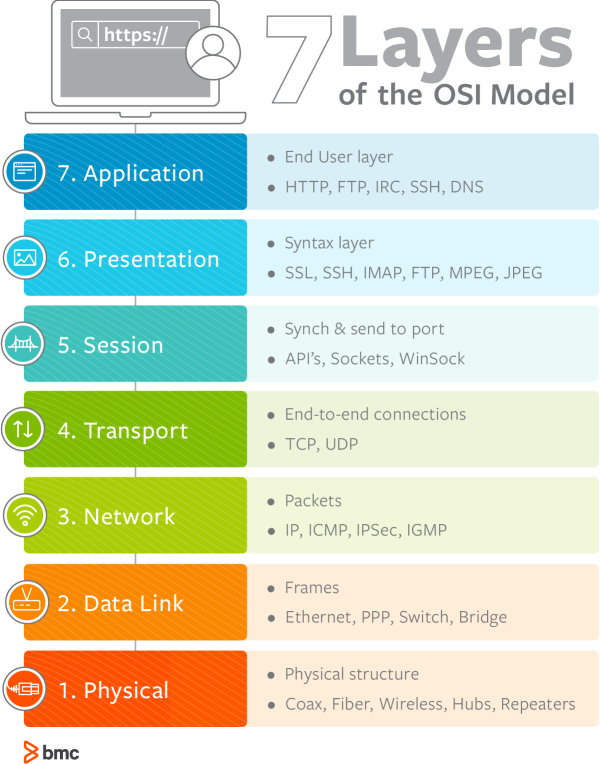
1. Physical
The lowest layer of the OSI model is concerned with data communication in the form of electrical, optic, or electromagnetic signals physically transmitting information between networking devices and infrastructure. The physical layer is responsible for the communication of unstructured raw data streams over a physical medium. It defines a range of aspects, including:
- Electrical, mechanical, and physical systems and networking devices that include specifications such as cable size, signal frequency, voltages, etc.
- Topologies such as Bus, Star, Ring, and Mesh
- Communication modes such as Simplex, Half Duplex, and Full Duplex
- Data transmission performance, such as Bit Rate and Bit Synchronization
- Modulation, switching, and interfacing with the physical transmission medium
- Common protocols including Wi-Fi, Ethernet, and others
- Hardware including networking devices, antennas, cables, modem, and intermediate devices such as repeaters and hubs
2. Data Link
The second layer of the OSI model concerns data transmission between the nodes within a network and manages the connections between physically connected devices such as switches. The raw data received from the physical layer is synchronized and packaged into data frames that contain the necessary protocols to route information between appropriate nodes. The data link layer is further divided into two sublayers:
- The Logical Link Control (LLC) sublayer is responsible for flow controls and error controls that ensure error-free and accurate data transmission between the network nodes.
- The Media Access Control (MAC) sublayer is responsible for managing access and permissions to transmit data between the network nodes. The data is transmitted sequentially and the layer expects acknowledgement for the encapsulated raw data sent between the nodes.
The third layer of the OSI model organizes and transmits data between multiple networks.
The network layer is responsible for routing the data via the best physical path based on a range of factors including network characteristics, best available path, traffic controls , congestion of data packets, and priority of service, among others. The network layer implements logical addressing for data packets to distinguish between the source and destination networks.
Other functions include encapsulation and fragmentation , congestion controls, and error handling. The outgoing data is divided into packets and incoming data is reassembled into information that is consumable at a higher application level. Network layer hardware includes routes, bridge routers, 3-layer switches, and protocols such as Internet (IPv4) Protocol version 4 and Internet Protocol version 6 (IPv6).
4. Transport
The fourth layer of the OSI model ensures complete and reliable delivery of data packets.
- The transport layer provides mechanisms such as error control, flow control, and congestion control to keep track of the data packets, check for errors and duplication, and resend the information that fails delivery. It involves the service-point addressing function to ensure that the packet is sent in response to a specific process (via a port address).
- Packet Segmentation and reassembly ensure that the data is divided and sequentially sent to the destination where it is rechecked for integrity and accuracy based on the receiving sequence.
Common protocols include the Transmission Control Protocol (TCP) for connection-oriented data transmission and User Datagram Protocol (UDP) for connectionless data transmission.
As the first of three layers that deal with the software level, the session layer manages sessions between servers to coordinate communication. Session refers to any interactive data exchange between two entities within a network. Common examples include HTTPS sessions that allow Internet users to visit and browse websites for a specific time period. The Session Layer is responsible for a range of functions including opening, closing, and re-establishing session activities, authentication and authorization of communication between specific apps and servers, identifying full-duplex or half-duplex operations, and synchronizing data streams.
Common Session Layer protocols include:
- Remote procedure call protocol (RPC)
- Point-to-Point Tunneling Protocol (PPTP)
- Session Control Protocol (SCP)
- Session Description Protocol (SDP), as described here
6. Presentation
The sixth layer of the OSI model converts data formats between applications and the networks. Responsibilities of the presentation layer include:
- Data conversion
- Character code translation
- Data compression
- Encryption and decryption
The presentation layer, also called the syntax layer, maps the semantics and syntax of the data such that the received information is consumable for every distinct network entity. For example, the data we transfer from our encryption-based communication app is formatted and encrypted at this layer before it is sent across the network.
At the receiving end, the data is decrypted and formatted into text or media information as originally intended. The presentation layer also serializes complex information into transportable formats. The data streams are then deserialized and reassembled into original object format at the destination.
7. Application
The application layer concerns the networking processes at the application level. This layer interacts directly with end-users to provide support for email, network data sharing, file transfers, and directory services, among other distributed information services. The upper most layer of the OSI model identifies networking entities to facilitate networking requests by end-user requests, determines resource availability, synchronizes communication, and manages application-specific networking requirements. The application layer also identifies constraints at the application level such as those associated with authentication, privacy, quality of service, networking devices, and data syntax.
Common application layer protocols include:
- File Transfer Protocol (FTP)
- Simple Mail Transfer Protocol (SMTP)
- Domain Name System (DNS)
The internet doesn’t welcome OSI
The OSI model is widely criticized for an inherent implementation complexity that renders networking operations inefficient and slow. The academic approach to developing the OSI protocol suite relied on replacing existing protocols across all communication layers with better alternatives.
This approach failed to gain traction in the industry; vendors had already invested significant resources in TCP/IP products and had to manage interoperability with the vast choices of protocols and specifications offered by the OSI model. Additionally, academia itself considered the OSI model as an invention politically inspired by the European telecommunication and U.S. government authorities.
The older TCP/IP architecture model had already itself in real-world network environments. It served as a solid foundation for the Internet–including all of the security , privacy, and performance-related challenges. Continued research and development, investments, and industry-wide adoption of the OSI model could have made today’s cyber world a different (and perhaps better) place, but the pragmatism of the TCP/IP model gave us the internet that prevails today.
Additional resources
Learn more with these resources:
- BMC IT Operations Blog
- IT Infrastructure Management: An Introduction
- IT Infrastructure Planning: Getting Started
- Network Engineer vs Network Administrator: Roles, Responsibilities, and Job Descriptions
- What Is a Virtual Network?
Original reference image:
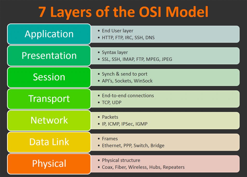
New strategies for modern service assurance
86% of global IT leaders in a recent IDG survey find it very, or extremely, challenging to optimize their IT resources to meet changing business demands.

These postings are my own and do not necessarily represent BMC's position, strategies, or opinion.
See an error or have a suggestion? Please let us know by emailing [email protected] .
Business, Faster than Humanly Possible
BMC works with 86% of the Forbes Global 50 and customers and partners around the world to create their future. With our history of innovation, industry-leading automation, operations, and service management solutions, combined with unmatched flexibility, we help organizations free up time and space to become an Autonomous Digital Enterprise that conquers the opportunities ahead. Learn more about BMC ›
You may also like

Why The Future of Service and Operations Management is Here Now

How to Use Automation in Event Remediation

Concerns and Challenges of IT Leaders Considering AIOps Platforms

Enterprise Networking Explained: Types, Concepts & Trends

BMC Helix Continuous Optimization: A Crucial Solution for Compliance in Financial Institutions

Insourcing vs Outsourcing IT Services: Comparing Your Options
About the author.
Muhammad Raza
Muhammad Raza is a Stockholm-based technology consultant working with leading startups and Fortune 500 firms on thought leadership branding projects across DevOps, Cloud, Security and IoT.
Presentation Layer: Protocols, Examples, Services | Functions of Presentation Layer
Presentation Layer is the 6th layer in the Open System Interconnection (OSI) model where all application programmer consider data structure and presentation, beyond of simply sending the data into form of datagram otherwise packets in between the hosts. Now, we will explain about what is presentation layer with its protocols, example, service ; involving with major functions of presentation Layer with ease. At the end of this article, you will completely educate about What is Presentation Layer in OSI Model without any hassle.
- What is Presentation Layer?
Definition : Presentation layer is 6th layer in the OSI model , and its main objective is to present all messages to upper layer as a standardized format. It is also known as the “ Translation layer “. This layer takes care of syntax and semantics of messages exchanged in between two communication systems. Presentation layer has responsible that receiver can understand all data, and it will be to implement all data languages can be dissimilar of two communication system.

Presentation layer is capable to handle abstract data structures, and further it helps to defined and exchange of higher-level data structures.
Presentation Layer Tutorial Headlines:
In this section, we will show you all headlines about this entire article; you can check them as your choice; below shown all:
- Functions of Presentation Layer
Protocols of Presentation Layer
- Example of Presentation Layer Protocols
Presentation Layer Services
Design issues with presentation layer, faqs (frequently asked questions), what is meant by presentation layer in osi model, what protocols are used in the presentation layer, can you explain some presentation layer examples, what are the main functions of the presentation layer, what are services of presentation layer in osi, let’s get started, functions of presentation layer.
Presentation layer performs various functions in the OSI model ; below explain each one –
- Presentation layer helps to translate from American standard code for information interchange (ASCII) to the extended binary code decimal interchange code (EBCDIC).
- It deals with user interface as well as supporting for several services such as email and file transfer.
- It provides encoding mechanism for translating all messages from user dependent format with common format and vice – versa.
- It’s main goal for data encryption and decryption of entire data before they are getting transmission over all common platforms.
- It provides data compression mechanism for source point to decrease the all bits which are transmitted. Due to this data compression system, user are able to transmit enlarge multimedia file at fastest file transfer rate.
- Due to use of Data Encryption and Decryption algorithm, presentation layer provides more network protection and confidentiality while transmission data over the entire network.
- This layer offers best flexibility for data translation for making connections with various kinds of servers , computers, and mainframes over the similar network.
- Presentation layer has responsible to fix all translations in between all network systems .
Presentation layer is used various protocols; below list is available –
- Multipurpose Internet Mail Extensions
- File Transfer Protocol
- Network News Transfer Protocol
- Apple Filing Protocol (AFP)
- Independent Computing Architecture (ICA), the Citrix system core protocol
- Lightweight Presentation Protocol (LPP)
- NetWare Core Protocol (NCP)
- Network Data Representation (NDR)
- Telnet (a remote terminal access protocol)
- Tox Protocol
- eXternal Data Representation (XDR)
- 25 Packet Assembler/Disassembler Protocol (PAD)
Example of Presentation Layer Protocols:
Here, we will discuss all examples of presentation layer protocols; below explain each one –
Multipurpose Internet Mail Extensions (MIME) : MIME protocol was introduced by Bell Communications in 1991, and it is an internet standard that provides scalable capable of email for attaching of images, sounds and text in a message.
File Transfer Protocol (FTP) : FTP is a internet protocol, and its main goal is to transmit all files in between one host to other hosts over the internet on TCP/IP connections.
Network News Transfer Protocol (NNTP) : This protocol is used to make connection with Usenet server and transmit all newsgroup articles in between system over internet.
Apple Filing Protocol (AFP ) : AFP protocol is designed by Apple company for sharing all files over the entire network .
Lightweight Presentation Protocol (LPP) : This protocol is used to offer ISO presentation services on top of TCP/IP based protocol stacks.
NetWare Core Protocol (NCP) : NCP is a Novell client server model protocol that is designed especially for Local Area Network (LAN). It is capable to perform several functions like as file/print-sharing, clock synchronization, remote processing and messaging.
Network Data Representation (NDR) : NDR is an data encoding standard, and it is implement in the Distributed Computing Environment (DCE).
Telnet (Telecommunication Network) : Telnet protocol was introduced in 1969, and it offers the command line interface for making communication along with remote device or server .
Tox : The Tox protocol is sometimes regarded as part of both the presentation and application layer , and it is used for sending peer-to-peer instant-messaging as well as video calling.
eXternal Data Representation (XDR) : This protocol provides the description and encoding of entire data, and it’s main goal is to transfer data in between dissimilar computer architecture.
25 Packet Assembler/Disassembler Protocol (PAD) : Main objective of this protocol is to obtain all data from group of terminal and allots the data into X. 25 packets.
Presentation layer provides several services like as –
- Data conversion
- Character code translation
- Compression
- Encryption and Decryption
- It helps to handle and maintain Syntax and Semantics of the message transmitted.
- Encoding data can be done as standard agreed like as String, double, date, and more.
- Standard Encoding can be done on wire.
Presentation Layer is the 6th layer in the Open System Interconnection (OSI) model that is the lowest layer, where all application programmer consider data structure and presentation, beyond of simply sending the data into form of datagram otherwise packets in between the hosts.
Presentation layer is used various protocols like as:
Yes! In this article, already we have been explained many examples of presentation layer; you can check them.
Presentation layer has a responsibility for formatting, translation, and delivery of the information for getting to process otherwise display .
Now, i hope that you have completely learnt about what is presentation layer with its protocols, example, service ; involving with major functions of presentation Layer with ease. If this post is useful for you, then please share it along with your friends, family members or relatives over social media platforms like as Facebook, Instagram, Linked In, Twitter, and more.
Also Read: Data Link Layer: Protocols, Examples | Functions of Data Link Layer
If you have any experience, tips, tricks, or query regarding this issue? You can drop a comment!
Related Posts

Computer Network
- Operating Systems
- Computer Fundamentals
- Interview Q
Physical Layer
Data link layer, network layer, routing algorithm, transport layer, application layer, application protocols, network security.
Interview Questions

- Send your Feedback to [email protected]
Help Others, Please Share

Learn Latest Tutorials

Transact-SQL

Reinforcement Learning

R Programming

React Native

Python Design Patterns

Python Pillow

Python Turtle

Preparation

Verbal Ability
Company Questions
Trending Technologies

Artificial Intelligence

Cloud Computing

Data Science

Machine Learning

B.Tech / MCA

Data Structures

Operating System

Compiler Design

Computer Organization

Discrete Mathematics

Ethical Hacking

Computer Graphics

Software Engineering

Web Technology

Cyber Security

C Programming

Control System

Data Mining

Data Warehouse


Introducing Copilot+ PCs
May 20, 2024 | Yusuf Mehdi - Executive Vice President, Consumer Chief Marketing Officer
- Share on Facebook (opens new window)
- Share on Twitter (opens new window)
- Share on LinkedIn (opens new window)

An on-demand recording of our May 20 event is available .
Today, at a special event on our new Microsoft campus, we introduced the world to a new category of Windows PCs designed for AI, Copilot+ PCs.
Copilot+ PCs are the fastest, most intelligent Windows PCs ever built. With powerful new silicon capable of an incredible 40+ TOPS (trillion operations per second), all – day battery life and access to the most advanced AI models, Copilot+ PCs will enable you to do things you can’t on any other PC. Easily find and remember what you have seen in your PC with Recall, generate and refine AI images in near real-time directly on the device using Cocreator, and bridge language barriers with Live Captions, translating audio from 40+ languages into English .
These experiences come to life on a set of thin, light and beautiful devices from Microsoft Surface and our OEM partners Acer, ASUS, Dell, HP, Lenovo and Samsung, with pre-orders beginning today and availability starting on June 18. Starting at $999, Copilot+ PCs offer incredible value.
This first wave of Copilot+ PCs is just the beginning. Over the past year, we have seen an incredible pace of innovation of AI in the cloud with Copilot allowing us to do things that we never dreamed possible. Now, we begin a new chapter with AI innovation on the device. We have completely reimagined the entirety of the PC – from silicon to the operating system, the application layer to the cloud – with AI at the center, marking the most significant change to the Windows platform in decades.
YouTube Video
The fastest, most secure Windows PCs ever built
We introduced an all-new system architecture to bring the power of the CPU, GPU, and now a new high performance Neural Processing Unit (NPU) together. Connected to and enhanced by the large language models (LLMs) running in our Azure Cloud in concert with small language models (SLMs), Copilot+ PCs can now achieve a level of performance never seen before. They are up to 20x more powerful [1] and up to 100x as efficient [2] for running AI workloads and deliver industry-leading AI acceleration. They outperform Apple’s MacBook Air 15” by up to 58% in sustained multithreaded performance [3] , all while delivering all-day battery life. With incredible efficiency, Copilot+ PCs can deliver up to 22 hours of local video playback or 15 hours of web browsing on a single charge. [4] That is up to 20% more battery in local video playback than the MacBook Air 15”. [5]
Windows now has the best implementation of apps on the fastest chip, starting with Qualcomm. We now offer more native Arm64 experiences than ever before, including our fastest implementation of Microsoft 365 apps like Teams, PowerPoint, Outlook, Word, Excel, OneDrive and OneNote. Chrome, Spotify, Zoom, WhatsApp, Adobe Photoshop, Adobe Lightroom, Blender, Affinity Suite, DaVinci Resolve and many more now run natively on Arm to give you great performance with additional apps, like Slack, releasing later this year. In fact, 87% of the total app minutes people spend in apps today have native Arm versions. [6] With a powerful new emulator, Prism, your apps run great, whether native or emulated.
Every Copilot+ PC comes secured out of the box. The Microsoft Pluton Security processor will be enabled by default on all Copilot+ PCs and we have introduced a number of new features, updates and defaults to Windows 11 that make it easy for users to stay secure. And, we’ve built in personalized privacy controls to help you protect what’s important to you. You can read more about how we are making Windows more secure here .
Entirely new, powerful AI experiences
Copilot+ PCs leverage powerful processors and multiple state-of-the-art AI models, including several of Microsoft’s world-class SLMs, to unlock a new set of experiences you can run locally, directly on the device. This removes previous limitations on things like latency, cost and even privacy to help you be more productive, creative and communicate more effectively.
Recall instantly
We set out to solve one of the most frustrating problems we encounter daily – finding something we know we have seen before on our PC. Today, we must remember what file folder it was stored in, what website it was on, or scroll through hundreds of emails trying to find it.
Now with Recall, you can access virtually what you have seen or done on your PC in a way that feels like having photographic memory. Copilot+ PCs organize information like we do – based on relationships and associations unique to each of our individual experiences. This helps you remember things you may have forgotten so you can find what you’re looking for quickly and intuitively by simply using the cues you remember. [7]
You can scroll across time to find the content you need in your timeline across any application, website, document, or more. Interact intuitively using snapshots with screenray to help you take the next step using suggested actions based on object recognition. And get back to where you were, whether to a specific email in Outlook or the right chat in Teams.
Recall leverages your personal semantic index, built and stored entirely on your device. Your snapshots are yours; they stay locally on your PC. You can delete individual snapshots, adjust and delete ranges of time in Settings, or pause at any point right from the icon in the System Tray on your Taskbar. You can also filter apps and websites from ever being saved. You are always in control with privacy you can trust.
Cocreate with AI-powered image creation and editing, built into Windows
Since the launch of Image Creator, almost 10 billion images have been generated, helping more people bring their ideas to life easily by using natural language to describe what they want to create. Yet, today’s cloud offerings may limit the number of images you can create, keep you waiting while the artwork processes or even present privacy concerns. By using the Neural Processing Units (NPUs) and powerful local small language models, we are bringing innovative new experiences to your favorite creative applications like Paint and Photos.
Combine your ink strokes with text prompts to generate new images in nearly real time with Cocreator. As you iterate, so does the artwork, helping you more easily refine, edit and evolve your ideas. Powerful diffusion-based algorithms optimize for the highest quality output over minimum steps to make it feel like you are creating alongside AI. Use the creativity slider to choose from a range of artwork from more literal to more expressive. Once you select your artwork, you can continue iterating on top of it, helping you express your ideas, regardless of your creative skills.

Take photo editing and image creation to the next level. With Restyle Image, you can reimagine your personal photos with a new style combining image generation and photo editing in Photos. Use a pre-set style like Cyberpunk or Claymation to change the background, foreground or full picture to create an entirely new image. Or jumpstart your next creative project and get visual inspiration with Image Creator in Photos. On Copilot+ PCs you can generate endless images for free, fast, with the ability to fine tune images to your liking and to save your favorites to collections.
Innovative AI experiences from the creative apps you love
We are also partnering with some of the biggest and most-loved applications on the planet to leverage the power of the NPU to deliver new innovative AI experiences.
Together with Adobe, we are thrilled to announce Adobe’s flagship apps are coming to Copilot+ PCs, including Photoshop, Lightroom and Express – available today. Illustrator, Premiere Pro and more are coming this summer. And we’re continuing to partner to optimize AI in these apps for the NPU. For Adobe Creative Cloud customers, they will benefit from the full performance advantages of Copilot+ PCs to express their creativity faster than ever before.

DaVinci Resolve Studio
Effortlessly apply visual effects to objects and people using NPU-accelerated Magic Mask in DaVinci Resolve Studio.

Remove the background from any video clip in a snap using Auto Cutout running on the NPU in CapCut.
Stay in your flow with faster, more responsive adaptive input controls, like head movement or facial expressions via the new NPU-powered camera pipeline in Cephable.

LiquidText
Make quicker and smarter annotations to documents, using AI features that run entirely on-device via NPU, so data stays private in LiquidText.

Have fun breaking down and remixing any music track, with a new, higher-quality version of NeuralMix™ that’s exclusive to NPU in Algoriddim’s djay Pro.

Connect and communicate effortlessly with live captions
In an increasingly connected and global world, Windows wants to bring people closer together. Whether catching up on your favorite podcast from a different country, or watching your favorite international sports team, or even collaborating with friends and colleagues across the world, we want to make more content accessible to more people.
Live Captions now has live translations and will turn any audio that passes through your PC into a single, English-language caption experience, in real time on your screen across all your apps consistently. You can translate any live or pre-recorded audio in any app or video platform from over 40 languages into English subtitles instantly, automatically and even while you’re offline. Powered by the NPU and available across all Copilot+ PCs, now you can have confidence your words are understood as intended.
New and enhanced Windows Studio Effects
Look and sound your best automatically with easily accessible controls at your fingertips in Quick Settings. Portrait light automatically adjusts the image to improve your perceived illumination in a dark environment or brighten the foreground pixels when in a low-light environment. Three new creative filters (illustrated, animated or watercolor) add an artistic flare. Eye contact teleprompter helps you maintain eye contact while reading your screen. New improvements to voice focus and portrait blur help ensure you’re always in focus.
Copilot, your everyday AI companion

Every Copilot+ PC comes with your personal powerful AI agent that is just a single tap away on keyboards with the new Copilot key. [8] Copilot will now have the full application experience customers have been asking for in a streamlined, simple yet powerful and personal design. Copilot puts the most advanced AI models at your fingertips. In the coming weeks, get access to the latest models including GPT-4o from our partners at OpenAI, so you can have voice conversations that feel more natural.
Advancing AI responsibly
At Microsoft, we have a company-wide commitment to develop ethical, safe and secure AI. Our responsible AI principles guided the development of these new experiences, and all AI features are aligned with our standards. Learn more here .
New Copilot+ PCs from Microsoft Surface and our partners
We have worked with each of the top OEMs — Acer, ASUS, Dell, HP, Lenovo, Samsung — and of course Surface, to bring exciting new Copilot+ PCs that will begin to launch on June 18. Starting at $999, these devices are up to $200 less than similar spec’d devices [9] .
Surface plays a key role in the Windows ecosystem, as we design software and hardware together to deliver innovative designs and meaningful experiences to our customers and fans. We are introducing the first-ever Copilot+ PCs from Surface: The all-new Surface Pro and Surface Laptop.

The new Surface Laptop is a powerhouse in an updated, modern laptop design with razor-thin bezels, a brilliant touchscreen display, AI-enhanced camera, premium audio, and now with a haptic touchpad.
Choose between a 13.8” and 15” display and four stunning colors. Enjoy up to 22 hours of local video playback on Surface Laptop 15” or up to 20 hours on Surface Laptop13.8” on top of incredible performance and all-new AI experiences.
The new Surface Pro is the most flexible 2-in-1 laptop, now reimagined with more speed and battery life to power all-new AI experiences. It introduces a new, optional OLED with HDR display, and ultrawide field of view camera perfect for Windows Studio Effects. The new Surface Pro Flex Keyboard is the first 2-in-1 keyboard designed to be used both attached or detached. It delivers enhanced stability, with Surface Slim Pen storage and charging integrated seamlessly, as well as a quiet, haptic touchpad. Learn more here.
New Copilot+ PCs from the biggest brands available starting June 18:
- Acer : Acer’s Swift 14 AI 2.5K touchscreen enables you to draw and edit your vision with greater accuracy and with color-accurate imagery. Launch and discover AI-enhanced features, like Acer PurifiedVoice 2.0 and Purified View, with a touch of the dedicated AcerSense button.
- ASUS : The ASUS Vivobook S 15 is a powerful device that brings AI experiences to life with its Snapdragon X Elite Platform and built-in Qualcomm® AI. It boasts 40+ NPU TOPS, a dual-fan cooling system, and up to 1 TB of storage. Next-gen AI enhancements include Windows Studio effects v2 and ASUS AiSense camera, with presence-detection capabilities for Adaptive Dimming and Lock. Built for portability, it has an ultra-slim and light all-metal design, a high-capacity battery, and premium styling with a single-zone RGB backlit keyboard.
- Dell : Dell is launching five new Copilot+ PCs, including the XPS 13, Inspiron 14 Plus, Inspiron 14, Latitude 7455, and Latitude 5455, offering a range of consumer and commercial options that deliver groundbreaking battery life and unique AI experiences. The XPS 13 is powered by Snapdragon X Elite processors and features a premium, futuristic design, while the Latitude 7455 boasts a stunning QHD+ display and quad speakers with AI noise reduction. The Inspiron14 and Inspiron 14 Plus feature a Snapdragon X Plus 1and are crafted with lightweight, low carbon aluminum and are energy efficient with EPEAT Gold rating.
- HP : HP’s OmniBook X AI PC and HP EliteBook Ultra G1q AI PC with Snapdragon X Elite are slim and sleek designs, delivering advanced performance and mobility for a more personalized computing experience. Features include long-lasting battery life and AI-powered productivity tools, such as real-time transcription and meeting summaries. A 5MP camera with automatic framing and eye focus is supported by Poly Studio’s crystal-clear audio for enhanced virtual interactions.
- Lenovo : Lenovo is launching two AI PCs: one built for consumers, Yoga Slim 7x, and one for commercial, ThinkPad T14s Gen 6. The Yoga Slim 7x brings efficiency for creatives, featuring a 14.5” touchscreen with 3K Dolby Vision and optimized power for 3D rendering and video editing. The T14s Gen 6 brings enterprise-level experiences and AI performance to your work tasks, with features including a webcam privacy shutter, Wi-Fi 7 connectivity and up to 64GB RAM.
- Samsung : Samsung’s new Galaxy Book4 Edge is ultra-thin and light, with a 3K resolution 2x AMOLED display and Wi-Fi 7 connectivity. It has a long-lasting battery that provides up to 22 hours of video playback, making it perfect for work or entertainment on the go.
Learn more about new Copilot+ PCs and pre-order today at Microsoft.com and from major PC manufacturers, as well as other leading global retailers.
Start testing for commercial deployment today
Copilot+ PCs offer businesses the most performant Windows 11 devices with unique AI capabilities to unlock productivity, improve collaboration and drive efficiency. As a Windows PC, businesses can deploy and manage a Copilot+ PC with the same tools and processes used today including IT controls for new features and AppAssure support. We recommend IT admins begin testing and readying for deployment to start empowering your workforce with access to powerful AI features on these high-performance devices. You can read more about our commercial experiences here .

AI innovation across the Windows ecosystem
Like we’ve always done with Windows, we have built a platform for our ecosystem partners to build on.
The first Copilot+ PCs will launch with both the Snapdragon® X Elite and Snapdragon® X Plus processors and feature leading performance per watt thanks to the custom Qualcomm Oryon™ CPU, which delivers unrivaled performance and battery efficiency. Snapdragon X Series delivers 45 NPU TOPS all-in-one system on a chip (SoC). The premium integrated Qualcomm® Adreno ™ GPU delivers stunning graphics for immersive entertainment. We look forward to expanding through deep partnerships with Intel and AMD, starting with Lunar Lake and Strix Point. We will bring new Copilot+ PC experiences at a later date. In the future we expect to see devices with this silicon paired with powerful graphics cards like NVIDIA GeForce RTX and AMD Radeon™, bringing Copilot+ PC experiences to reach even broader audiences like advanced gamers and creators.
We are at an inflection point where the PC will accelerate AI innovation. We believe the richest AI experiences will only be possible when the cloud and device work together in concert. Together with our partners, we’re setting the frame for the next decade of Windows innovation.
[1] Based on snapshot of aggregated, non-gaming app usage data as of April 2024 for iGPU-based laptops and 2-in-1 devices running Windows 10 and Windows 11 in US, UK, CA, FR, AU, DE, JP.
[2] Tested April 2024 using Phi SLM workload running 512-token prompt processing in a loop with default settings comparing pre-release Copilot+ PC builds with Snapdragon Elite X 12 Core and Snapdragon X Plus 10 core configurations (QNN build) to Windows 11 PC with NVIDIA 4080 GPU configuration (CUDA build).
[3] Tested May 2024 using Cinebench 2024 Multi-Core benchmark comparing Copilot+ PCs with Snapdragon X Elite 12 core and Snapdragon X Plus 10 core configurations to MacBook Air 15” with M3 8 core CPU / 10 Core GPU configuration. Performance will vary significantly between device configuration and usage.
[4] *Battery life varies significantly by device and with settings, usage and other factors. See aka.ms/cpclaims*
[5] *Battery life varies significantly based on device configuration, usage, network and feature configuration, signal strength, settings and other factors. Testing conducted May 2024 using the prelease Windows ADK full screen local video playback assessment under standard testing conditions, with the device connected to Wi-Fi and screen brightness set to 150 nits, comparing Copilot+ PCs with Snapdragon X Elite 12 core and Snapdragon X Plus 10 core configurations running Windows Version 26097.5003 (24H2) to MacBook Air 15” M3 8-Core CPU/ 10 Core GPU running macOS 14.4 with similar device configurations and testing scenario.
[6] Based on snapshot of aggregated, non-gaming app usage data as of April 2024 for iGPU-based laptops and 2-in-1 devices running Windows 10 and Windows 11 in US, UK, CA, FR, AU, DE, JP.
[7] Recall is optimized for select languages (English, Chinese (simplified), French, German, Japanese, and Spanish.) Content-based and storage limitations apply. Learn more here .
[8] Copilot key functionality may vary. See aka.ms/keysupport
[9] Based on MSRPs; actual savings may vary
Tags: AI , Copilot+ PC
- Check us out on RSS
COMMENTS
Introduction : Presentation Layer is the 6th layer in the Open System Interconnection (OSI) model. This layer is also known as Translation layer, as this layer serves as a data translator for the network. ... The physical layer consists of various networking devices such as connectors, receivers, plugs, modems, repeaters, cables, Hubs, etc. The ...
The Session Layer initiates, maintains, and terminates connections between two end-user applications. It responds to requests from the presentation layer and issues requests to the transport layer. OSI Layer 6. Layer 6 is the presentation layer. This layer is responsible for data formatting, such as character encoding and conversions, and data ...
The presentation layer is the lowest layer at which application programmers consider data structure and presentation, instead of simply sending data in the form of datagrams or packets between hosts. This layer deals with issues of string representation - whether they use the Pascal method (an integer length field followed by the specified ...
The presentation layer ensures the information that the application layer of one system sends out is readable by the application layer of another system. On the sending system it is responsible for conversion to standard, transmittable formats. [7] On the receiving system it is responsible for the translation, formatting, and delivery of ...
The sixth layer of the OSI model is the Presentation layer. Applications running on the local system may or may not understand the format that is used to transmit the data over the network. ... This layer specifies the standards for devices, media, and technologies that are used in moving the data across the network such as:-Type of cable used ...
The tool that manages Hypertext Transfer Protocol is an example of a program that loosely adheres to the presentation layer of OSI.Although it's technically considered an application-layer protocol per the TCP/IP model, HTTP includes presentation layer services within it.HTTP works when the requesting device forwards user requests passed to the web browser onto a web server elsewhere in the ...
Data Link Layer. Network Layer. Transport Layer. Session Layer. Presentation Layer. Application Layer. Summary. The Open Systems Interconnection (OSI) networking model defines a conceptual framework for communications between computer systems. The model is an ISO standard which identifies seven fundamental networking layers, from the physical ...
The presentation layer. ... It ensures that the pace of the data flow doesn't overwhelm the sending and receiving devices. This layer also permits the transmission of data to Layer 3, the network layer, where it's addressed and routed. The data-link layer can be further divided into two sublayers.
Physical layer: First and lowest layer of the OSI model. It is used for data transmission and defines the physical connection between the sending and receiving devices, providing security for the ...
The presentation layer takes care of getting data ready for the application layer. The two devices that are communicating may use different methods of encoding their data. Layer 6 therefore turns the incoming data into something that can be read at the application layer. This includes encrypting and decrypting data.
Presentation Layer is the Layer 6 of the seven-layer Open Systems Interconnection ... HTTP works when the requesting device forwards user requests passed to the web browser onto a web server elsewhere in the network. It receives a return message from the web server that includes a multipurpose internet mail extensions (MIME) header. ...
Key functions of the Presentation Layer in the OSI model include: Data Encryption: It securely encrypts data to prevent unauthorized access during transmission. Data Compression: It reduces data ...
Raw data is located on the Presentation Layer. The main job of this layer is to process the data before it can be used by the OSI application layer. ... Devices: modem, RF links, cables, hub, repeater, voltage regulators and routing devices. Basic protocols: Integrated Services Digital Network (ISDN), Recommended Standard 232 (RS232/EIA232 ...
Starting from the top layer and going towards the bottom, here are the seven layers of the OSI model: 1. Application layer 2. Presentation layer 3. Session layer 4. Transport layer 5. Network layer 6. Data link layer 7. Physical layer. Let's take a closer look at each of these layers. 1. Application Layer This is the layer where humans ...
The Presentation Layer is a crucial component of the OSI model, responsible for ensuring that data exchanged between systems is in a format that can be understood and used. By performing functions such as data translation, formatting, compression, and encryption, the Presentation Layer plays a vital role in maintaining data integrity ...
The session layer is the fifth layer of the OSI layers model. It is responsible for initiating, establishing, managing, and terminating sessions between the local application and the remote applications. It defines standards for three modes of communication: full duplex, half-duplex, and simplex. In the full duplex mode, both devices can send ...
The presentation layer prepares data for the application layer. It defines how two devices should encode, encrypt, and compress data so it is received correctly on the other end. The presentation layer takes any data transmitted by the application layer and prepares it for transmission over the session layer. 5. Session Layer. The session layer ...
Hardware including networking devices, antennas, cables, modem, and intermediate devices such as repeaters and hubs; 2. Data Link. The second layer of the OSI model concerns data transmission between the nodes within a network and manages the connections between physically connected devices such as switches.
Presentation Layer: The presentation layer is layer 6 of the 7-layer Open Systems Interconnection (OSI) model. It is used to present data to the application layer (layer 7) in an accurate, well-defined and standardized format. The presentation layer is sometimes called the syntax layer.
Telnet (Telecommunication Network): Telnet protocol was introduced in 1969, and it offers the command line interface for making communication along with remote device or server. Tox: The Tox protocol is sometimes regarded as part of both the presentation and application layer, and it is used for sending peer-to-peer instant-messaging as well as video calling.
The presentation layer is the 6 th layer from the bottom in the OSI model. This layer presents the incoming data from the application layer of the sender machine to the receiver machine. It converts one format of data to another format of data if both sender and receiver understand different formats; hence this layer is also called the ...
Now, we begin a new chapter with AI innovation on the device. We have completely reimagined the entirety of the PC - from silicon to the operating system, the application layer to the cloud - with AI at the center, marking the most significant change to the Windows platform in decades.