Layer 6 Presentation Layer
De/Encryption, Encoding, String representation
The presentation layer (data presentation layer, data provision level) sets the system-dependent representation of the data (for example, ASCII, EBCDIC) into an independent form, enabling the syntactically correct data exchange between different systems. Also, functions such as data compression and encryption are guaranteed that data to be sent by the application layer of a system that can be read by the application layer of another system to the layer 6. The presentation layer. If necessary, the presentation layer acts as a translator between different data formats, by making an understandable for both systems data format, the ASN.1 (Abstract Syntax Notation One) used.

OSI Layer 6 - Presentation Layer
The presentation layer is responsible for the delivery and formatting of information to the application layer for further processing or display. It relieves the application layer of concern regarding syntactical differences in data representation within the end-user systems. An example of a presentation service would be the conversion of an EBCDIC-coded text computer file to an ASCII-coded file. The presentation layer is the lowest layer at which application programmers consider data structure and presentation, instead of simply sending data in the form of datagrams or packets between hosts. This layer deals with issues of string representation - whether they use the Pascal method (an integer length field followed by the specified amount of bytes) or the C/C++ method (null-terminated strings, e.g. "thisisastring\0"). The idea is that the application layer should be able to point at the data to be moved, and the presentation layer will deal with the rest. Serialization of complex data structures into flat byte-strings (using mechanisms such as TLV or XML) can be thought of as the key functionality of the presentation layer. Encryption is typically done at this level too, although it can be done on the application, session, transport, or network layers, each having its own advantages and disadvantages. Decryption is also handled at the presentation layer. For example, when logging on to bank account sites the presentation layer will decrypt the data as it is received.[1] Another example is representing structure, which is normally standardized at this level, often by using XML. As well as simple pieces of data, like strings, more complicated things are standardized in this layer. Two common examples are 'objects' in object-oriented programming, and the exact way that streaming video is transmitted. In many widely used applications and protocols, no distinction is made between the presentation and application layers. For example, HyperText Transfer Protocol (HTTP), generally regarded as an application-layer protocol, has presentation-layer aspects such as the ability to identify character encoding for proper conversion, which is then done in the application layer. Within the service layering semantics of the OSI network architecture, the presentation layer responds to service requests from the application layer and issues service requests to the session layer. In the OSI model: the presentation layer ensures the information that the application layer of one system sends out is readable by the application layer of another system. For example, a PC program communicates with another computer, one using extended binary coded decimal interchange code (EBCDIC) and the other using ASCII to represent the same characters. If necessary, the presentation layer might be able to translate between multiple data formats by using a common format. Wikipedia
- Data conversion
- Character code translation
- Compression
- Encryption and Decryption
The Presentation OSI Layer is usually composed of 2 sublayers that are:
CASE common application service element
Sase specific application service element, layer 7 application layer, layer 6 presentation layer, layer 5 session layer, layer 4 transport layer, layer 3 network layer, layer 2 data link layer, layer 1 physical layer.
The OSI Model – The 7 Layers of Networking Explained in Plain English

This article explains the Open Systems Interconnection (OSI) model and the 7 layers of networking, in plain English.
The OSI model is a conceptual framework that is used to describe how a network functions. In plain English, the OSI model helped standardize the way computer systems send information to each other.
Learning networking is a bit like learning a language - there are lots of standards and then some exceptions. Therefore, it’s important to really understand that the OSI model is not a set of rules. It is a tool for understanding how networks function.
Once you learn the OSI model, you will be able to further understand and appreciate this glorious entity we call the Internet, as well as be able to troubleshoot networking issues with greater fluency and ease.
All hail the Internet!
Prerequisites
You don’t need any prior programming or networking experience to understand this article. However, you will need:
- Basic familiarity with common networking terms (explained below)
- A curiosity about how things work :)
Learning Objectives
Over the course of this article, you will learn:
- What the OSI model is
- The purpose of each of the 7 layers
- The problems that can happen at each of the 7 layers
- The difference between TCP/IP model and the OSI model
Common Networking Terms
Here are some common networking terms that you should be familiar with to get the most out of this article. I’ll use these terms when I talk about OSI layers next.
A node is a physical electronic device hooked up to a network, for example a computer, printer, router, and so on. If set up properly, a node is capable of sending and/or receiving information over a network.
Nodes may be set up adjacent to one other, wherein Node A can connect directly to Node B, or there may be an intermediate node, like a switch or a router, set up between Node A and Node B.
Typically, routers connect networks to the Internet and switches operate within a network to facilitate intra-network communication. Learn more about hub vs. switch vs. router.
Here's an example:

For the nitpicky among us (yep, I see you), host is another term that you will encounter in networking. I will define a host as a type of node that requires an IP address. All hosts are nodes, but not all nodes are hosts. Please Tweet angrily at me if you disagree.
Links connect nodes on a network. Links can be wired, like Ethernet, or cable-free, like WiFi.
Links to can either be point-to-point, where Node A is connected to Node B, or multipoint, where Node A is connected to Node B and Node C.
When we’re talking about information being transmitted, this may also be described as a one-to-one vs. a one-to-many relationship.
A protocol is a mutually agreed upon set of rules that allows two nodes on a network to exchange data.
“A protocol defines the rules governing the syntax (what can be communicated), semantics (how it can be communicated), and synchronization (when and at what speed it can be communicated) of the communications procedure. Protocols can be implemented on hardware, software, or a combination of both. Protocols can be created by anyone, but the most widely adopted protocols are based on standards.” - The Illustrated Network.
Both wired and cable-free links can have protocols.
While anyone can create a protocol, the most widely adopted protocols are often based on standards published by Internet organizations such as the Internet Engineering Task Force (IETF).
A network is a general term for a group of computers, printers, or any other device that wants to share data.
Network types include LAN, HAN, CAN, MAN, WAN, BAN, or VPN. Think I’m just randomly rhyming things with the word can ? I can ’t say I am - these are all real network types. Learn more here .
Topology describes how nodes and links fit together in a network configuration, often depicted in a diagram. Here are some common network topology types:

A network consists of nodes, links between nodes, and protocols that govern data transmission between nodes.
At whatever scale and complexity networks get to, you will understand what’s happening in all computer networks by learning the OSI model and 7 layers of networking.
What is the OSI Model?
The OSI model consists of 7 layers of networking.
First, what’s a layer?

No, a layer - not a lair . Here there are no dragons.
A layer is a way of categorizing and grouping functionality and behavior on and of a network.
In the OSI model, layers are organized from the most tangible and most physical, to less tangible and less physical but closer to the end user.
Each layer abstracts lower level functionality away until by the time you get to the highest layer. All the details and inner workings of all the other layers are hidden from the end user.
How to remember all the names of the layers? Easy.
- Please | Physical Layer
- Do | Data Link Layer
- Not | Network Layer
- Tell (the) | Transport Layer
- Secret | Session Layer
- Password (to) | Presentation Layer
- Anyone | Application Layer
Keep in mind that while certain technologies, like protocols, may logically “belong to” one layer more than another, not all technologies fit neatly into a single layer in the OSI model. For example, Ethernet, 802.11 (Wifi) and the Address Resolution Protocol (ARP) procedure operate on >1 layer.
The OSI is a model and a tool, not a set of rules.
OSI Layer 1
Layer 1 is the physical layer . There’s a lot of technology in Layer 1 - everything from physical network devices, cabling, to how the cables hook up to the devices. Plus if we don’t need cables, what the signal type and transmission methods are (for example, wireless broadband).
Instead of listing every type of technology in Layer 1, I’ve created broader categories for these technologies. I encourage readers to learn more about each of these categories:
- Nodes (devices) and networking hardware components. Devices include hubs, repeaters, routers, computers, printers, and so on. Hardware components that live inside of these devices include antennas, amplifiers, Network Interface Cards (NICs), and more.
- Device interface mechanics. How and where does a cable connect to a device (cable connector and device socket)? What is the size and shape of the connector, and how many pins does it have? What dictates when a pin is active or inactive?
- Functional and procedural logic. What is the function of each pin in the connector - send or receive? What procedural logic dictates the sequence of events so a node can start to communicate with another node on Layer 2?
- Cabling protocols and specifications. Ethernet (CAT), USB, Digital Subscriber Line (DSL) , and more. Specifications include maximum cable length, modulation techniques, radio specifications, line coding, and bits synchronization (more on that below).
- Cable types. Options include shielded or unshielded twisted pair, untwisted pair, coaxial and so on. Learn more about cable types here .
- Signal type. Baseband is a single bit stream at a time, like a railway track - one-way only. Broadband consists of multiple bit streams at the same time, like a bi-directional highway.
- Signal transmission method (may be wired or cable-free). Options include electrical (Ethernet), light (optical networks, fiber optics), radio waves (802.11 WiFi, a/b/g/n/ac/ax variants or Bluetooth). If cable-free, then also consider frequency: 2.5 GHz vs. 5 GHz. If it’s cabled, consider voltage. If cabled and Ethernet, also consider networking standards like 100BASE-T and related standards.
The data unit on Layer 1 is the bit.
A bit the smallest unit of transmittable digital information. Bits are binary, so either a 0 or a 1. Bytes, consisting of 8 bits, are used to represent single characters, like a letter, numeral, or symbol.
Bits are sent to and from hardware devices in accordance with the supported data rate (transmission rate, in number of bits per second or millisecond) and are synchronized so the number of bits sent and received per unit of time remains consistent (this is called bit synchronization). The way bits are transmitted depends on the signal transmission method.
Nodes can send, receive, or send and receive bits. If they can only do one, then the node uses a simplex mode. If they can do both, then the node uses a duplex mode. If a node can send and receive at the same time, it’s full-duplex – if not, it’s just half-duplex.
The original Ethernet was half-duplex. Full-duplex Ethernet is an option now, given the right equipment.
How to Troubleshoot OSI Layer 1 Problems
Here are some Layer 1 problems to watch out for:
- Defunct cables, for example damaged wires or broken connectors
- Broken hardware network devices, for example damaged circuits
- Stuff being unplugged (...we’ve all been there)
If there are issues in Layer 1, anything beyond Layer 1 will not function properly.
Layer 1 contains the infrastructure that makes communication on networks possible.
It defines the electrical, mechanical, procedural, and functional specifications for activating, maintaining, and deactivating physical links between network devices. - Source
Fun fact: deep-sea communications cables transmit data around the world. This map will blow your mind: https://www.submarinecablemap.com/
And because you made it this far, here’s a koala:

OSI Layer 2
Layer 2 is the data link layer . Layer 2 defines how data is formatted for transmission, how much data can flow between nodes, for how long, and what to do when errors are detected in this flow.
In more official tech terms:
- Line discipline. Who should talk for how long? How long should nodes be able to transit information for?
- Flow control. How much data should be transmitted?
- Error control - detection and correction . All data transmission methods have potential for errors, from electrical spikes to dirty connectors. Once Layer 2 technologies tell network administrators about an issue on Layer 2 or Layer 1, the system administrator can correct for those errors on subsequent layers. Layer 2 is mostly concerned with error detection, not error correction. ( Source )
There are two distinct sublayers within Layer 2:
- Media Access Control (MAC): the MAC sublayer handles the assignment of a hardware identification number, called a MAC address, that uniquely identifies each device on a network. No two devices should have the same MAC address. The MAC address is assigned at the point of manufacturing. It is automatically recognized by most networks. MAC addresses live on Network Interface Cards (NICs). Switches keep track of all MAC addresses on a network. Learn more about MAC addresses on PC Mag and in this article . Learn more about network switches here .
- Logical Link Control (LLC): the LLC sublayer handles framing addressing and flow control. The speed depends on the link between nodes, for example Ethernet or Wifi.
The data unit on Layer 2 is a frame .
Each frame contains a frame header, body, and a frame trailer:
- Header: typically includes MAC addresses for the source and destination nodes.
- Body: consists of the bits being transmitted.
- Trailer: includes error detection information. When errors are detected, and depending on the implementation or configuration of a network or protocol, frames may be discarded or the error may be reported up to higher layers for further error correction. Examples of error detection mechanisms: Cyclic Redundancy Check (CRC) and Frame Check Sequence (FCS). Learn more about error detection techniques here .

Typically there is a maximum frame size limit, called an Maximum Transmission Unit, MTU. Jumbo frames exceed the standard MTU, learn more about jumbo frames here .
How to Troubleshoot OSI Layer 2 Problems
Here are some Layer 2 problems to watch out for:
- All the problems that can occur on Layer 1
- Unsuccessful connections (sessions) between two nodes
- Sessions that are successfully established but intermittently fail
- Frame collisions
The Data Link Layer allows nodes to communicate with each other within a local area network. The foundations of line discipline, flow control, and error control are established in this layer.
OSI Layer 3
Layer 3 is the network layer . This is where we send information between and across networks through the use of routers. Instead of just node-to-node communication, we can now do network-to-network communication.
Routers are the workhorse of Layer 3 - we couldn’t have Layer 3 without them. They move data packets across multiple networks.
Not only do they connect to Internet Service Providers (ISPs) to provide access to the Internet, they also keep track of what’s on its network (remember that switches keep track of all MAC addresses on a network), what other networks it’s connected to, and the different paths for routing data packets across these networks.
Routers store all of this addressing and routing information in routing tables.
Here’s a simple example of a routing table:

The data unit on Layer 3 is the data packet . Typically, each data packet contains a frame plus an IP address information wrapper. In other words, frames are encapsulated by Layer 3 addressing information.
The data being transmitted in a packet is also sometimes called the payload . While each packet has everything it needs to get to its destination, whether or not it makes it there is another story.
Layer 3 transmissions are connectionless, or best effort - they don't do anything but send the traffic where it’s supposed to go. More on data transport protocols on Layer 4.
Once a node is connected to the Internet, it is assigned an Internet Protocol (IP) address, which looks either like 172.16. 254.1 (IPv4 address convention) or like 2001:0db8:85a3:0000:0000:8a2e:0370:7334 (IPv6 address convention). Routers use IP addresses in their routing tables.
IP addresses are associated with the physical node’s MAC address via the Address Resolution Protocol (ARP), which resolves MAC addresses with the node’s corresponding IP address.
ARP is conventionally considered part of Layer 2, but since IP addresses don’t exist until Layer 3, it’s also part of Layer 3.
How to Troubleshoot OSI Layer 3 Problems
Here are some Layer 3 problems to watch out for:
- All the problems that can crop up on previous layers :)
- Faulty or non-functional router or other node
- IP address is incorrectly configured
Many answers to Layer 3 questions will require the use of command-line tools like ping , trace , show ip route , or show ip protocols . Learn more about troubleshooting on layer 1-3 here .
The Network Layer allows nodes to connect to the Internet and send information across different networks.
OSI Layer 4
Layer 4 is the transport layer . This where we dive into the nitty gritty specifics of the connection between two nodes and how information is transmitted between them. It builds on the functions of Layer 2 - line discipline, flow control, and error control.
This layer is also responsible for data packet segmentation, or how data packets are broken up and sent over the network.
Unlike the previous layer, Layer 4 also has an understanding of the whole message, not just the contents of each individual data packet. With this understanding, Layer 4 is able to manage network congestion by not sending all the packets at once.
The data units of Layer 4 go by a few names. For TCP, the data unit is a packet. For UDP, a packet is referred to as a datagram. I’ll just use the term data packet here for the sake of simplicity.
Transmission Control Protocol (TCP) and User Datagram Protocol (UDP) are two of the most well-known protocols in Layer 4.
TCP, a connection-oriented protocol, prioritizes data quality over speed.
TCP explicitly establishes a connection with the destination node and requires a handshake between the source and destination nodes when data is transmitted. The handshake confirms that data was received. If the destination node does not receive all of the data, TCP will ask for a retry.
TCP also ensures that packets are delivered or reassembled in the correct order. Learn more about TCP here .
UDP, a connectionless protocol, prioritizes speed over data quality. UDP does not require a handshake, which is why it’s called connectionless.
Because UDP doesn’t have to wait for this acknowledgement, it can send data at a faster rate, but not all of the data may be successfully transmitted and we’d never know.
If information is split up into multiple datagrams, unless those datagrams contain a sequence number, UDP does not ensure that packets are reassembled in the correct order. Learn more about UDP here .
TCP and UDP both send data to specific ports on a network device, which has an IP address. The combination of the IP address and the port number is called a socket.
Learn more about sockets here .
Learn more about the differences and similarities between these two protocols here .
How to Troubleshoot OSI Layer 4 Problems
Here are some Layer 4 problems to watch out for:
- Blocked ports - check your Access Control Lists (ACL) & firewalls
- Quality of Service (QoS) settings. QoS is a feature of routers/switches that can prioritize traffic, and they can really muck things up. Learn more about QoS here .
The Transport Layer provides end-to-end transmission of a message by segmenting a message into multiple data packets; the layer supports connection-oriented and connectionless communication.
OSI Layer 5
Layer 5 is the session layer . This layer establishes, maintains, and terminates sessions.
A session is a mutually agreed upon connection that is established between two network applications. Not two nodes! Nope, we’ve moved on from nodes. They were so Layer 4.
Just kidding, we still have nodes, but Layer 5 doesn’t need to retain the concept of a node because that’s been abstracted out (taken care of) by previous layers.
So a session is a connection that is established between two specific end-user applications. There are two important concepts to consider here:
- Client and server model: the application requesting the information is called the client, and the application that has the requested information is called the server.
- Request and response model: while a session is being established and during a session, there is a constant back-and-forth of requests for information and responses containing that information or “hey, I don’t have what you’re requesting.”
Sessions may be open for a very short amount of time or a long amount of time. They may fail sometimes, too.
Depending on the protocol in question, various failure resolution processes may kick in. Depending on the applications/protocols/hardware in use, sessions may support simplex, half-duplex, or full-duplex modes.
Examples of protocols on Layer 5 include Network Basic Input Output System (NetBIOS) and Remote Procedure Call Protocol (RPC), and many others.
From here on out (layer 5 and up), networks are focused on ways of making connections to end-user applications and displaying data to the user.
How to Troubleshoot OSI Layer 5 Problems
Here are some Layer 5 problems to watch out for:
- Servers are unavailable
- Servers are incorrectly configured, for example Apache or PHP configs
- Session failure - disconnect, timeout, and so on.
The Session Layer initiates, maintains, and terminates connections between two end-user applications. It responds to requests from the presentation layer and issues requests to the transport layer.
OSI Layer 6
Layer 6 is the presentation layer . This layer is responsible for data formatting, such as character encoding and conversions, and data encryption.
The operating system that hosts the end-user application is typically involved in Layer 6 processes. This functionality is not always implemented in a network protocol.
Layer 6 makes sure that end-user applications operating on Layer 7 can successfully consume data and, of course, eventually display it.
There are three data formatting methods to be aware of:
- American Standard Code for Information Interchange (ASCII): this 7-bit encoding technique is the most widely used standard for character encoding. One superset is ISO-8859-1, which provides most of the characters necessary for languages spoken in Western Europe.
- Extended Binary-Coded Decimal Interchange Code (EBDCIC): designed by IBM for mainframe usage. This encoding is incompatible with other character encoding methods.
- Unicode: character encodings can be done with 32-, 16-, or 8-bit characters and attempts to accommodate every known, written alphabet.
Learn more about character encoding methods in this article , and also here .
Encryption: SSL or TLS encryption protocols live on Layer 6. These encryption protocols help ensure that transmitted data is less vulnerable to malicious actors by providing authentication and data encryption for nodes operating on a network. TLS is the successor to SSL.
How to Troubleshoot OSI Layer 6 Problems
Here are some Layer 6 problems to watch out for:
- Non-existent or corrupted drivers
- Incorrect OS user access level
The Presentation Layer formats and encrypts data.
OSI Layer 7
Layer 7 is the application layer .
True to its name, this is the layer that is ultimately responsible for supporting services used by end-user applications. Applications include software programs that are installed on the operating system, like Internet browsers (for example, Firefox) or word processing programs (for example, Microsoft Word).
Applications can perform specialized network functions under the hood and require specialized services that fall under the umbrella of Layer 7.
Electronic mail programs, for example, are specifically created to run over a network and utilize networking functionality, such as email protocols, which fall under Layer 7.
Applications will also control end-user interaction, such as security checks (for example, MFA), identification of two participants, initiation of an exchange of information, and so on.
Protocols that operate on this level include File Transfer Protocol (FTP), Secure Shell (SSH), Simple Mail Transfer Protocol (SMTP), Internet Message Access Protocol (IMAP), Domain Name Service (DNS), and Hypertext Transfer Protocol (HTTP).
While each of these protocols serve different functions and operate differently, on a high level they all facilitate the communication of information. ( Source )
How to Troubleshoot OSI Layer 7 Problems
Here are some Layer 7 problems to watch out for:
- All issues on previous layers
- Incorrectly configured software applications
- User error (... we’ve all been there)
The Application Layer owns the services and functions that end-user applications need to work. It does not include the applications themselves.
Our Layer 1 koala is all grown up.

Learning check - can you apply makeup to a koala?
Don’t have a koala?
Well - answer these questions instead. It’s the next best thing, I promise.
- What is the OSI model?
- What are each of the layers?
- How could I use this information to troubleshoot networking issues?
Congratulations - you’ve taken one step farther to understanding the glorious entity we call the Internet.
Learning Resources
Many, very smart people have written entire books about the OSI model or entire books about specific layers. I encourage readers to check out any O’Reilly-published books about the subject or about network engineering in general.
Here are some resources I used when writing this article:
- The Illustrated Network, 2nd Edition
- Protocol Data Unit (PDU): https://www.geeksforgeeks.org/difference-between-segments-packets-and-frames/
- Troubleshooting Along the OSI Model: https://www.pearsonitcertification.com/articles/article.aspx?p=1730891
- The OSI Model Demystified: https://www.youtube.com/watch?v=HEEnLZV2wGI
- OSI Model for Dummies: https://www.dummies.com/programming/networking/layers-in-the-osi-model-of-a-computer-network/
Chloe Tucker is an artist and computer science enthusiast based in Portland, Oregon. As a former educator, she's continuously searching for the intersection of learning and teaching, or technology and art. Reach out to her on Twitter @_chloetucker and check out her website at chloe.dev .
Read more posts .
If you read this far, thank the author to show them you care. Say Thanks
Learn to code for free. freeCodeCamp's open source curriculum has helped more than 40,000 people get jobs as developers. Get started
The OSI Model’s 7 Layers, Explained
The seven layers in the Open Systems Interconnection (OSI) model each serve a specific function and work together to create an efficient network communication system.
The Open Systems Interconnection (OSI) model is a framework in network communication that simplifies complex network interactions into a structured format.
What Is the OSI Model?
The Open Systems Interconnection model is a framework in network communication designed to simplify complex network interactions into a structured format. This architecture has seven layers, each of which serves a specific function. All seven layers work together to create a robust and efficient network communication system.
Each of its seven layers has a distinct role, ensuring efficient data transfer from one device to another . The OSI model is essential for understanding how data is transmitted in a network and is also a practical guide for network protocol design and problem solving.
learn more about cybersecurity An Introduction to Microsegmentation in Network Security
The OSI model, developed by the International Organization for Standardization , outlines the essential functions of networking and telecommunications systems for practical application. It plays a crucial role in telecommunications, where vendors use it to define the features and capabilities of their products and services.
This approach allows for a detailed explanation of different aspects of network communication, including transport protocols, addressing schemes and data packaging methods. As a result, the OSI model resolves the complexities of network communication and fosters a more integrated and coherent digital world .
The 7 Layers of the OSI Model
Each layer of the OSI model serves a specific function, yet they work in harmony to create a robust and efficient network communication system. Understanding these layers provides valuable insights into the complexities of network design and operation, showcasing the intricate nature of modern digital communication.
Layer 7: Application Layer
Functionality: The Application Layer is the closest to the end user. It facilitates user interaction with networked systems, providing interfaces and protocols for web browsers, email clients and other applications.
Key protocols: Protocols like HTTP, FTP and SMTP operate at this layer, enabling services such as web browsing, file transfers and email communications.
Layer 6: Presentation Layer
Role: The Presentation Layer acts as a translator, converting data formats from the application layer into a network-compatible format and vice versa. It ensures that data sent from one system is readable by another.
Data formatting: This layer is responsible for data encryption and compression, playing a significant role in maintaining data privacy and efficient transmission.
Layer 5: Session Layer
Managing sessions: It establishes, manages and terminates sessions between applications. This layer ensures that sessions are maintained for the duration of the communication.
Coordination: The Session Layer coordinates communication between systems, managing dialogues and synchronizing data exchange.
Layer 4: Transport Layer
Data segmentation and control: The Transport Layer is crucial for segmenting data into smaller packets. It ensures end-to-end data integrity and delivery, managing flow control, error correction and sequencing.
Protocols: TCP (Transmission Control Protocol) and UDP (User Datagram Protocol) are key protocols in this layer, differing in their approach to data transmission.
Layer 3: Network Layer
Routing and addressing: This layer is responsible for logical addressing and routing data packets across different networks. It determines the best path for data to travel from source to destination.
Internet protocol: The Internet Protocol (IP), fundamental for internet data exchange, operates at this layer.
Layer 2: Data Link Layer
Framing and MAC addressing: The Data Link Layer frames data into packets. It handles physical addressing through MAC addresses, ensuring that data is directed to the correct hardware.
Error detection: This layer is also involved in error detection and handling, improving overall data transmission reliability.
Layer 1: Physical Layer
Physical transmission: The Physical Layer deals with the physical aspects of data transmission, including cable types, electrical signals and data rates.
Hardware components: It involves hardware components like cables, switches and network interface cards, forming the foundation of network communication.
How Data Flows in the OSI Model
Understanding this data flow process is crucial for professionals, as it aids in diagnosing and troubleshooting network issues, designing efficient network solutions and ensuring robust data security and management.
Encapsulation Process
When data is sent, it begins at the Application Layer and moves down through the layers. At each stage, it is encapsulated with the necessary headers, trailers, and other control information relevant to that layer. For instance, at the Transport Layer, data is segmented and encapsulated with port numbers, while at the Network Layer, IP addresses are added.
Each layer plays a role in preparing the data for transmission. The Presentation Layer may encrypt the data for security, while the Data Link Layer ensures it is formatted into frames suitable for physical transmission.
Data Transmission Across the Network
The Physical Layer transmits the raw bits over a physical medium, such as a cable or wireless network. This transmission is the actual movement of data across the network. In cases where data must move across different networks, the Network Layer’s routing functionalities become crucial. It ensures that data packets find the most efficient path to their destination.
Decapsulation Process
Upon reaching the destination, the data moves up the OSI model, with each layer removing its respective encapsulation. The Data Link Layer, for instance, removes framing, and the Transport Layer checks for transmission errors and reassembles the data segments. Once the data reaches the Application Layer, it is in its original format and ready to be used by the receiving application, whether it’s an email client, a web browser or any other networked software.
Seamless Data Flow
The OSI model ensures that each layer only communicates with its immediate upper and lower layers, creating a seamless flow. This layered approach means changes in one layer’s protocols or functionalities can occur without disrupting the entire network.
OSI Model Advantages
The OSI model is a cornerstone in network architecture for several reasons:
Simplification of network design
The OSI model’s layered approach breaks down complex network processes, making design and operation more manageable. Each layer focuses on a specific aspect of communication, allowing for independent development and easier troubleshooting.
Standardization and interoperability
It establishes universal standards for network communication, enabling different technologies to interact seamlessly. This interoperability is crucial for the efficient functioning of diverse network devices and applications.
Flexibility and Scalability
Adaptable to technological advancements, the OSI model allows individual layers to evolve without overhauling the entire system. This scalability makes it suitable for various network sizes and types.
Enhanced Security
Security measures are integrated at multiple layers, providing a robust defense against threats. Each layer can address specific security concerns, leading to comprehensive network protection.
Real-World Applications of the OSI Model
The OSI model’s influence extends well beyond theoretical concepts, playing a crucial role in various practical aspects of networking:
Network Design and Protocol Development
Network professionals use the OSI model as a blueprint for structuring and developing robust networks. It guides the creation of new protocols, ensuring seamless integration and functionality across different network layers.
Efficient Troubleshooting and Management
In troubleshooting, the OSI model provides a systematic approach for identifying issues, from physical connectivity to application-level errors. It also aids in network maintenance and performance optimization, addressing each layer to enhance overall efficiency.
Cybersecurity Strategy
The model is foundational in crafting layered security strategies . By implementing security measures at different layers, it offers comprehensive protection against various cyber threats. Understanding the OSI layers is key in detecting and mitigating attacks targeting specific network segments.
Educational and Training Tool
It serves as an essential framework in networking education, helping students and professionals alike understand complex network operations. The OSI model is a cornerstone in training programs , emphasizing the intricacies of network architecture and security.
safety first When and How to Run a Phishing Simulation
OSI Model vs. TCP/IP Model
While the OSI model offers a detailed conceptual framework, the TCP/IP model is recognized for its practical application in today’s internet-driven world.
Structural Differences
OSI model : Introduced as a comprehensive, protocol-independent framework, the OSI model details seven distinct layers, offering a more granular approach to network communication.
TCP/IP model : Developed earlier by the U.S. Department of Defense, the TCP/IP model consists of four layers (Application, Transport, Internet and Network Access), combining certain OSI layers.
Theoretical vs. Practical Approach
OSI model : Developed as a theoretical and universal networking model, it’s used more for educational purposes to explain how networks operate.
TCP/IP model : This model is designed around specific standard protocols, focusing on solving practical communication issues. It leaves sequencing and acknowledgment functions to the transport layer, differing from the OSI approach.
Adoption and Use
OSI model: While not widely implemented in its entirety, the OSI model’s clear layer separation is influential in protocol design and network education; simpler applications in the OSI framework may not utilize all seven layers, with only the first three layers (Physical, Data Link, and Network) being mandatory for basic data communication.
TCP/IP model : The dominant model used in most network architectures today, especially in internet-related communications. In TCP/IP, most applications engage all layers for communication.
Frequently Asked Questions
Why is the osi model important.
The OSI model is crucial for standardizing network communication and ensuring interoperability between various devices and systems. It simplifies network design and troubleshooting and serves as a fundamental educational tool in networking.
What are the 7 layers of the OSI model?
Layer 1: Physical Layer — Transmits raw data.
Layer 2: Data Link Layer — Manages direct links and framing.
Layer 3: Network Layer — Handles addressing and routing.
Layer 4: Transport Layer — Ensures reliable data transfer.
Layer 5: Session Layer — Manages connections.
Layer 6: Presentation Layer — Translates data formats.
Layer 7: Application Layer — Interfaces with applications.
Recent Expert Contributors Articles

OSI Seven Layers Model Explained with Examples
This tutorial explains the OSI reference model. Learn the seven layers of the OSI model and the functions of each layer in detail through examples.
The OSI (Open System Interconnection) reference model is a comprehensive set of standards and rules for hardware manufacturers and software developers. By following these standards, they can build networking components and software applications that work in any environment. It was published in 1984 by ISO (International Organization for Standardization).
It provides a framework for creating and implementing networking standards, devices, and internetworking schemes. It explains the networking from a modular perspective, making it easier to understand and troubleshoot.
Seven layers of the OSI Model
The OSI model has seven different layers, which are divided into two groups. The following table lists all the layers with their names and numbers.

Let’s understand each layer in detail.
This tutorial is the second part of the article " Networking reference models explained in detail with examples. ". Other parts of this article are the following.
This tutorial is the first part of the article. It summarizes why the OSI model was created and what advantages it has.
This tutorial is the third part of the article. It compares the OSI reference model with the TCP/IP model and lists the similarities and differences between both.
This tutorial is the fourth part of the article. It explains the five layers of the TCP/IP model in detail.
This tutorial is the fifth part of the article. It explains how data is encapsulated and de-encapsulated when it passes through the layers.
The Application Layer
This is the last and topmost layer of the OSI model. This layer provides an interface between the local system and the application program running on the network. If an application wants to use the resources available on the remote system, it interacts with this layer. Then, this layer provides the protocols and services that the application needs to access those resources.
There are two types of application programs: Network-aware and Network-unaware . An application program is considered a Network-aware application if it can make any type of network request. If an application program cannot make any type of network request, it is considered a Network-unaware program.
Network-aware programs are further divided into two types.
Programs that are mainly built to work on a local system. This type of program occasionally accesses the network for particular reasons such as updates, documentation, and troubleshooting. MS-Word, Adobe-Photoshop, and VLC Player are examples of this type of program.
Programs that are mainly built to work with a remote system. This type of program provides a platform to access resources available on a remote system. This type of program only works if the system is connected to the network. SSH, FTP, and TFTP are examples of this type of program.
The Application layer describes only the programs which fall in the second type. But it doesn’t mean that the first type of programs can’t take the advantage of the Application layer. It simply means that they are not documented in the Application layer. But if required, they can also connect to the network through the Application layer.
The Top layer of the OSI model is the application layer. It provides the protocols and services that are required by the network-aware applications to connect to the network. FTP, TFTP, POP3, SMTP, and HTTP are examples of standards and protocols used in this layer.
The Presentation Layer
The sixth layer of the OSI model is the Presentation layer. Applications running on the local system may or may not understand the format that is used to transmit the data over the network. The presentation layer works as a translator. When receiving data from the Application layer, it converts that data in such a format that can be sent over the network. When receiving data from the Session layer, it reconverts the data in such a format that the application, which will use it, can understand.
Conversion, compression, and encryption are the main functions that the Presentation layer performs on the sending computer while on the receiving computer these functions are reconversion, decompression, and decryption. ASCII, BMP, GIF, JPEG, WAV, AVI, and MPEG are examples of standards and protocols that work in this layer.
The Session Layer
The session layer is the fifth layer of the OSI model. It is responsible for setting up, managing, and dismantling sessions between presentation layer entities and providing dialogs between computers.
When an application makes a network request, this layer checks whether the requested resource is available on the local system or on a remote system. If the requested resource is available on a remote system, it tests whether a network connection to access that resource is available or not. If a network connection is not available, it sends an error message back to the application informing that the connection is not available.
If a network connection is available, it establishes a session with the remote system. For each request, it uses a separate session. This allows multiple applications to send or receive data simultaneously. When data transmission is completed, it terminates the session.
The session layer is responsible for establishing, managing, and terminating communications between two computers. RPCs and NFS are examples of the session layer.
The Transport Layer
The transport layer is the fourth layer of the OSI model. It provides the following functionalities: -
Segmentation
On the sending computer, it breaks the data stream into smaller pieces. Each piece is known as a segment and the process of breaking the data stream into smaller pieces is known as the segmentation . On the receiving computer, it joins all segments to recreate the original data stream.
Data transportation
This layer establishes a logical connection between the sending system and receiving system and uses that connection to provide end-to-end data transportation. This process uses two protocols: TCP and UDP.
The TCP protocol is used for reliable data transportation. TCP is a connection-oriented protocol. UDP protocol is used for unreliable data transportation. UDP is a connection-less protocol.
The main difference between a connection-less and connection-oriented protocol is that a connection-oriented protocol provides reliable data delivery. For reliable data delivery, it uses several mechanisms such as the three-way handshake process, acknowledgments, sequencing, and flow control.
Multiplexing
Through the use of port numbers, this layer also provides connection multiplexing. Connection multiplexing allows multiple applications to send and receive data simultaneously.
The main functionalities of the Transport layer are segmentation, data transportation, and connection multiplexing. For data transportation, it uses TCP and UDP protocols. TCP is a connection-oriented protocol. It provides reliable data delivery.
The Network Layer
The third layer of the OSI model is the Network Layer. This layer takes the data segment from the Transport layer and adds a logical address to it. A logical address has two components; network partition and host partition. The Network partition is used to group networking components while the host partition is used to uniquely identify a system on the network. A logical address is known as the IP address. Once the logical address and other related information are added to the segment , it becomes the packet .
This layer decides whether the packet is intended for the local system or a remote system. It also specifies the standards and protocols which are used to move data packets over networks.
To move data packets between two different networks, a device known as the router is used. Routers use the logical address to make the routing decision. Routing is the process of forwarding data packets to their destination.
Defining logical addresses and finding the best path to reach the destination address are the main functions of this layer. Routers work in this layer. Routing also takes place in this layer. IP, IPX, and AppleTalk are examples of this layer.
The Data Link Layer
The Data Link Layer is the second layer of the OSI model. This layer defines how networking components access the media and what transmission methods they use. This layer has two sub-layers: MAC and LLC.
MAC (Media Access Control)
This sub-layer defines how the data packets are placed in media. It also provides physical addressing. The physical address is known as the MAC address. Unlike logical addresses that need to be configured, physical addresses are pre-configured in NIC. The MAC address is used to uniquely identify a host in the local network.
LLC (Logical Link Control)
This sub-layer identifies the network layer protocol. On the sending computer, it encapsulates the information of the Network Layer protocol in the LLC header from which the Data Link layer receives the data packet. On the receiving computer, it checks the LLC header to get the information about the network layer protocol. This way, a data packet is always delivered to the same network layer protocol from which it was sent.
Defining physical addresses, finding hosts in the local network, specifying standards and methods to access the media are the primary functions of this layer. Switching takes place in this layer. Switches and Bridges work in this layer. HDLC, PPP, and Frame Relay are examples of this layer.
The Physical Layer
The Physical Layer is the first layer of the OSI model. This layer specifies the standards for devices, media, and technologies that are used in moving the data across the network such as:-
- Type of cable used in connecting the devices
- Patterns of pins used in both sides of the cable
- Type of interface-card used in the networking device
- Type of connector used to connect the cable with the network interface
- Encoding of digital signals received from the Data Link layer based on the attached media type such as electrical for copper, light for fiber, or a radio wave for wireless.
On the sending computer, it converts digital signals received from the Data Link layer, into analog signals and loads them on the physical media. On the receiving computer, it picks analog signals from the media and converts them into digital signals, and transfers them to the Data Link layer for further processing.
The Physical Layer mainly defines standards for media and devices that are used to move data across the network. 10BaseT, 10Base100, CSU/DSU, DCE, and DTE are examples of the standards used in this layer.
That’s all for this tutorial. In the next part of this article, we will compare the OSI model with the TCP/IP model and explains the similarities and differences between both models. If you like this tutorial, please don’t forget to share it with friends.
By ComputerNetworkingNotes Updated on 2024-01-25 05:30:01 IST
ComputerNetworkingNotes CCNA Study Guide OSI Seven Layers Model Explained with Examples
We do not accept any kind of Guest Post. Except Guest post submission, for any other query (such as adverting opportunity, product advertisement, feedback, suggestion, error reporting and technical issue) or simply just say to hello mail us [email protected]
PrepBytes Blog
ONE-STOP RESOURCE FOR EVERYTHING RELATED TO CODING
Sign in to your account
Forgot your password?
Login via OTP
We will send you an one time password on your mobile number
An OTP has been sent to your mobile number please verify it below
Register with PrepBytes
Presentation layer in osi model.

Last Updated on March 7, 2024 by Abhishek Sharma

The OSI (Open Systems Interconnection) model is a conceptual framework used to understand the functions of a telecommunication or computing system. It consists of seven layers, each responsible for specific tasks. The sixth layer, known as the Presentation Layer, plays a crucial role in ensuring that data exchanged between systems is readable and usable. Let’s explore the functions and importance of the Presentation Layer in the OSI model.
What is Presentation Layer in OSI Model?
The Presentation Layer, the sixth layer of the OSI (Open Systems Interconnection) model, is responsible for ensuring that data exchanged between systems is in a format that can be interpreted and used by the receiving system. It performs various functions, including data translation, encryption, compression, and formatting, to facilitate efficient and secure communication between networked devices.
Functions of the Presentation Layer
Below are some of the functions of the Presentation Layer in OSI Model:
- Data Translation: The Presentation Layer translates data from the format used by the application layer into a format that can be transmitted over the network. This includes encoding, compression, and encryption.
- Data Formatting: It ensures that data is formatted according to the specifications of the application layer. This includes converting between different character sets, such as ASCII and Unicode.
- Data Compression: The Presentation Layer compresses data to reduce the amount of bandwidth required for transmission, improving network efficiency.
- Data Encryption: It encrypts data to ensure that it remains secure during transmission, protecting it from unauthorized access.
- Data Syntax: The Presentation Layer defines the syntax for data representation, ensuring that both the sender and receiver understand the structure of the data being exchanged.
Importance of the Presentation Layer
Importance of Presentation Layer are:
- Data Integrity: By ensuring that data is formatted correctly and encrypted, the Presentation Layer helps maintain the integrity of data during transmission.
- Interoperability: The Presentation Layer enables different systems to communicate with each other by ensuring that data is translated into a common format that both systems understand.
- Efficiency: Data compression reduces the amount of data that needs to be transmitted, improving network efficiency and reducing bandwidth requirements.
- Security: Encryption provided by the Presentation Layer ensures that data remains secure and protected from unauthorized access.
Conclusion The Presentation Layer is a crucial component of the OSI model, responsible for ensuring that data exchanged between systems is in a format that can be understood and used. By performing functions such as data translation, formatting, compression, and encryption, the Presentation Layer plays a vital role in maintaining data integrity, facilitating interoperability, and ensuring the security of data during transmission.
FAQs related to Presentation Layer in OSI Model
Here are some of the FAQs related to Presentation Layer in OSI Model:
Q1: What is the role of the Presentation Layer in the OSI model? The Presentation Layer ensures that data exchanged between systems is in a usable format, performing functions such as data translation, encryption, compression, and formatting.
Q2: How does the Presentation Layer ensure data security? The Presentation Layer encrypts data before transmission, making it unreadable to unauthorized parties, thus ensuring data security.
Q3: Why is data compression important in the Presentation Layer? Data compression reduces the size of data packets, leading to faster transmission speeds and optimized bandwidth usage, which is crucial in high-traffic networks.
Q4: How does the Presentation Layer facilitate interoperability between systems? By translating data into a common format that both sender and receiver understand, the Presentation Layer enables different systems to communicate with each other seamlessly.
Q5: Can the Presentation Layer be bypassed in data transmission? While it is possible to bypass the Presentation Layer in some cases, doing so can lead to compatibility issues between systems and is not recommended.
Leave a Reply Cancel reply
Your email address will not be published. Required fields are marked *
Save my name, email, and website in this browser for the next time I comment.
- Linked List
- Segment Tree
- Backtracking
- Dynamic Programming
- Greedy Algorithm
- Operating System
- Company Placement
- Interview Tips
- General Interview Questions
- Data Structure
- Other Topics
- Computational Geometry
- Game Theory
Related Post
Securing routing protocols, redundant link problems, traditional wireless mobile communication, carrier sense multiple access (csma), quantum cryptography, introduction to sniffers.
What is the OSI Model? 7 layers explained in detail
Become a Software Engineer in Months, Not Years
From your first line of code, to your first day on the job — Educative has you covered. Join 2M+ developers learning in-demand programming skills.
Networking is a vast topic. The OSI model helps us better understand it. In this article, we will cover the OSI model. The Open Systems Interconnection (OSI) model is a conceptual framework that describes the functions of a networking or telecommunication system in seven layers.
The OSI model describes how a network functions and standardizes the way that systems send information to one another. In this article, we will introduce you to the OSI model and discuss each layer in detail.
We will cover the following:
What is the OSI Model?
- Layer 1: Physical
- Layer 2: Data Link
- Layer 3: Network
- Layer 4: Transport
- Layer 5: Session
- Layer 6: Presentation
- Layer 7: Application
Data flow example
What to learn next, take a deep dive on everything network-related this course will teach you the fundamentals of networks, socket programming in python, command-line tools and the main protocols of each layer. grokking computer networking for software engineers.
Developed in 1984, the Open Systems Interconnection or OSI model is a seven-layer model used to describe networking connections . It was initially developed by ISO, the International Organization for Standardization in 1984 and is now common practice for learning networking concepts.
The OSI models specifies how information is transmitted from a network device like a router to its destination through a physical medium and how it interacts with the application. In other words, it provides a standard for different systems to communicate with each other.
We will go through the different layers in detail below, but keep in mind that the upper layers (first 4) are about transport issues like the physical characteristics of the network and data transmission. The lower layers (last 3) are about application issues like data formatting and user interfacing.
Why should you learn this?
Some people argue that the OSI model is obsolete because it is less important than the four layers of the TCP/IP model, but this is not true. The OSI model is essential theory for understanding modern computer network technology in a connection-oriented way.
Most discussions on network communication include references to the OSI model and its conceptual framework.
The purpose of this model is to enhance interoperability and functionality between different vendors and connectors. It describes the functions of a networking system. From a design point of view, it divides larger tasks into smaller, more manageable ones.
The OSI model allows network administrators to focus on the design of particular layers. It is also useful when troubleshooting network problems by breaking them down and isolating the source.
Layer 1: Physical Layer
At the lowest layer of the OSI reference model, the physical layer is responsible for transmitting unstructured data bits across the network between the physical layers of the sending and receiving devices. In other words, it takes care of the transmission of raw bit streams.
The physical layer may include physical resources like cables, modems, network adapters, and hubs, etc.
Layer 2: Data Link Layer
The data link layer corrects any errors that may have occurred at the physical layer. It ensures that any data transfer is error-free between nodes over the physical layer. It is responsible for reliable transmission of data frames between connected nodes.
The data is packaged into frames here and transferred node-to-node. The data layer has the following sub-layers
- Media Access Control (MAC): The MAC address layer is responsible for flow control and multiplexing devices transmissions over the network.
- Logical link control (LLC): The LLC layer provides error control and flow control over the physical medium and identifies line protocols.
Keep the learning going.
Learn networking fundamentals without scrubbing through videos or documentation. Educative’s text-based courses are easy to skim and feature live coding environments, making learning quick and efficient.
Grokking Computer Networking for Software Engineers.
Layer 3: Network Layer
The network layer receives frames from the data link layer and delivers them to the intended destination based on the addresses inside the frame. It also handles packet routing. The network layer locates destinations using logical addresses like the IP. Routers are a crucial component at this layer as they route information to where it needs to go between different networks.
The main functions of the Network layer are:
- Routing: The network layer protocols determine which routes from source to destination.
- Logical Addressing: The network layer defines an addressing scheme to uniquely identify devices. The network layer places the IP addresses from the sender and receiver in the header.
Layer 4: Transport Layer
The transport layer is responsible for delivering, error checking, flow control , and sequencing data packets . It regulates the sequencing, size, and transfer of data between systems and hosts. It gets the data from the session layer and breaks it into transportable segments.
Two examples of the Transport Layer are the UDP (User Datagram Protocol) and TCP (Transmission Control Protocol) that is build on top of the Internet Protocol (IP model), which work at layer 3.
Layer 5: Session Layer
The session layer will create communication channels, called sessions , between different devices. This layer is responsible for opening those sessions and ensuring that they’re functional during data transfer.
In other words, the session layer is responsible for establishing, managing, and terminating communication sessions with the lower layers with the presentation and application layer. It is also responsible for authentication and reconnections, and it can set checkpoints during a data transfer—if.
Layer 6: Presentation Layer
The presentation layer is responsible for ensuring that the data is understandable for the end system or useful for later stages. It translates or formats data based on the application’s syntax or semantics. It also manages any encryption or decryption required by the application layer. It is also called the syntax layer .
Layer 7: Application Layer
The application layer is where the user directly interacts with a software application, so it is closest to the end user . When the user wants to transmit files or pictures, this layer interacts with the application communicating with the network. The application layer identifies resources, communication partners, and synchronizes communication.
Other functions of the application layer are the Network Virtual Terminal and FTAM-File transfer access, and mail/directory services. The protocol used depends on the information the user wants to send. Some common protocols include:
- POP3 or SMTP for emails
- FTP for emails
- Telnet for controlling remote devices
Examples of communications that use Layer 7 are web browsers (Chrome, Firefox, Safari).
Here is how data flows through the OSI model. Let’s say you send an email to a friend. Your email passes through the application layer to the presentation layer . This layer will compress your data.
Next, the session layer initializes communication. It will then be segmented in the transportation layer, broken up into packets in the network layer, and then into frames at the data link layer. It will then be sent to the physical layer where it is converted to 0s and 1s and sent through a physical medium like cables.
When your friend gets the email through the physical medium, the data flows through the same layers but in the opposite order . The physical layer will convert the 0s and 1s to frames that will be passed to the data link layer. This will reassemble the frames into packets for the next layer.
The network layer will assemble the segments into data. The data is then passed on to the presentation layer that ends the communication session. The presentation layer will then pass the data to the application layer. The application layer feeds the human-readable data to the email software that will allow your friend to read your email.
Congratulations on making it to the end. I hope you now know what the OSI model is, how the OSI layers work, and why you need to know about it. These concepts are essential for understanding how networks function.
This was just the beginning, and there is a lot you can learn. You can start with:
- Access networks
- Socket programming
To get hands on with these concepts, check out Educative’s course Grokking Computer Networking for Software Engineers. You will learn about networks, command-line tools, socket programming in Python, all in a hands-on environment. Any software engineer can benefit from a solid grasp on these concepts.
Happy learning!
Continue reading about networking
- Behind the Screens: What happens when you type a URL in a browser
- Computer Networking 101: Terms, Tools, and Getting Started
- Kerberos in 5 Minutes: Introducing network authentication
Learn in-demand tech skills in half the time
Mock Interview
Skill Paths
Assessments
Learn to Code
Tech Interview Prep
Generative AI
Data Science
Machine Learning
GitHub Students Scholarship
Early Access Courses
For Individuals
Try for Free
Gift a Subscription
Become an Author
Become an Affiliate
Earn Referral Credits
Cheatsheets
Frequently Asked Questions
Privacy Policy
Cookie Policy
Terms of Service
Business Terms of Service
Data Processing Agreement
Copyright © 2024 Educative, Inc. All rights reserved.
What is the OSI Model?
Explanation, layers, and data flows in the Open Systems Interconnection model.
Global Threat Landscape Report 2H 2023
Speak with an Expert

OSI Model Explained
The Open Systems Interconnection (OSI) model is a framework that describes the functions of a networking system. The OSI model categorizes the computing functions of the different network components, outlining the rules and requirement needed to support the interoperability of the software and hardware that make up the network.
In addition to understanding what the OSI model is, note that the OSI model layers are particularly helpful when visualizing the flow of data from the sender to the receiver. The descriptions of the various levels, as well as their interdependency, make it easier to pinpoint networking issues. Also, programmers can use the OSI model to better understand how data gets to and from their applications or to write code specific for use at certain levels.
In the following sections, you will see the OSI model explained.
FortiGuard Labs Global Threat Landscape Report 2H 2023 shows Cybercriminals Exploiting New Industry Vulnerabilities 43% Faster than 1H 2023.
What Are the 7 Layers of the OSI Model?
There are seven abstraction layers that make up the OSI model. Communication from one person to another goes from Layer 7 to Layer 1. Each layer performs a specific job before it sends the data on to the next layer.
Layer 7 - Application layer
The application layer is the closest to the end-user. It initiates communication between the user and the applications they personally interact with. At this layer, data is translated from the syntax it was converted to into something the user can read.
Examples of Layer 7 applications include a web browser like Chrome, Safari, or Firefox, or an email application. Layer 7 can also identify communication partners, check to see which resources are available, and make sure communication is properly synced.
Layer 6 - Presentation layer
The presentation layer takes care of getting data ready for the application layer. The two devices that are communicating may use different methods of encoding their data. Layer 6 therefore turns the incoming data into something that can be read at the application layer. This includes encrypting and decrypting data.
The presentation layer also compresses data that comes from the application layer before it sends it on to Layer 5, the session layer.
Layer 5 - Session layer
The session layer handles opening and closing network communications between two interacting devices. The “session” refers to the time between the opening and closing of the interaction. The session layer makes sure the session is open for a long enough period of time for all the necessary data to be sent through. The session layer then closes the session to prevent expending unnecessary resources.
Also, it synchronizes the data transfer. If a large amount of data is being sent, the session layer can set up checkpoints. If the transmission gets interrupted before all the data is downloaded, the checkpoints allow the transmission to be resumed without it starting all over again.
Layer 4 - Transport layer
The transport layer handles end-to-end communication between the devices interacting with each other. The management of the communication involves taking the data in the session layer and dividing it into pieces referred to as segments. The transport layer on the device receiving the communication handles the reassembly of the segments into data that is consumable by the session layer.
Also, the transport layer takes care of managing the flow and any necessary error messages that need to be sent in the event something goes wrong. To manage data flow, the transport layer makes sure it is not being sent so quickly that the receiver’s device cannot handle it. To control errors, the transport layer checks to see if the data transmitted was done so completely. If it is not, this layer will request a retransmission.
Layer 4 is where Transmission Control Protocol (TCP) and User Datagram Protocol (UDP) port numbers work. Internet Protocol (IP) addresses operate at Layer 3, the network layer. TCP, UDP, and IP are protocols that facilitate how data is sent and received.
Layer 3 - Network layer
The network layer facilitates the transfer of data when two networks are communicating with each other. If two communicating devices are using the same network, then there is no need for the network layer. The network layer divides the segments that come from the transport layer. These are referred to as packets. The division of the segments into packets happens on the sender’s device, and they are reassembled on the receiving device.
The network layer also functions as an efficiency tool. It figures out the optimal physical path needed to get the data to its destination. This function is called “routing.”
Layer 2 - Data link layer
The data link layer is like the network layer, except that the data link layer facilitates data transfer between two devices using the same network. In the data link layer, packets are broken into pieces referred to as frames. Similar to the network layer, the data link layer handles flow and error control. The transport layer is different in that it only manages the flow of data and errors when two networks are communicating with each other.
Within the data link layer, you have two sublayers, the media access control (MAC) and logical link control (LLC) layers. The majority of switches perform their duties at Layer 2. In some cases, switches work at Layer 3 because they are facilitating communication between two networks or virtual local-area networks (VLANs). This has to happen at Layer 3 because, in these situations, the data needs to be routed, which is a Layer 3 task.
Layer 1 - Physical layer
The physical layer involves the physical equipment that transfers data, like switches and cables. In this layer, the data is converted into strings of 1s and 0s. In the physical layer, the devices have to agree on a method of distinguishing the 1s from the 0s, which enables the digital data to be properly interpreted by each device.
The physical layer includes a variety of components, such as cables, the radio frequency used to transmit data, Wi-Fi, and the other physical structures for transmitting data, such as pins, necessary voltages, and types of ports.

How Data Flows through OSI Model Layers
Each of the seven OSI model layers communicates with layers below and above it. For example, the application layer interacts with software applications, while the presentation layer provides encryption and data compression. Likewise, the session layer creates communications between devices. The transport layer breaks data into chunks (called segments) to send them, then the receiving device reassembles the segments before the network layer breaks them into smaller packets to send to other networks. The data link layer facilitates data transfer between devices on the same network, and, finally, the physical layer transfers data in machine language (ones and zeros).
Frequently Asked Questions about OSI Model
What is osi model, why do we use the osi model.
OSI model layers are particularly helpful when visualizing the flow of data from the sender to the receiver. The descriptions of the various levels, as well as their interdependency, make it easier to pinpoint networking issues.
What are 7 layers of the OSI model?
Cybersecurity resources.
- Cybersecurity
- Types of Cyber Attacks
- IT vs OT Cybersecurity
- AI Cybersecurity
- Cyber Threat Intelligence
- Cybersecurity Management
- Network Security
- Data Security
- Email Security
- Endpoint Security
- Web Security
- Enterprise Security
- Cybersecurity Mesh
Quick Links
- Fortinet Products
- Fortinet Demos
- Analyst Reports
Related Topics
More resources, white papers, case studies.
Please fill out the form and a knowledgeable representative will get in touch with you soon.
By clicking submit you agree to the Fortinet Terms and Conditions & Privacy Policy .
- Engineering Mathematics
- Discrete Mathematics
- Operating System
- Computer Networks
- Digital Logic and Design
- C Programming
- Data Structures
- Theory of Computation
- Compiler Design
- Computer Org and Architecture
- Computer Network Tutorial
Basics of Computer Network
- Basics of Computer Networking
- Introduction to basic Networking Terminology
- Goals of Networks
- Basic characteristics of Computer Networks
- Challenges of Computer Network
- Physical Components of Computer Network
Network Hardware and Software
- Types of Computer Networks
- LAN Full Form
- How to Set Up a LAN Network?
- MAN Full Form in Computer Networking
- MAN Full Form
- WAN Full Form
- Introduction of Internetworking
- Difference between Internet, Intranet and Extranet
- Protocol Hierarchies in Computer Network
- Network Devices (Hub, Repeater, Bridge, Switch, Router, Gateways and Brouter)
- Introduction of a Router
- Introduction of Gateways
- What is a network switch, and how does it work?
Network Topology
- Types of Network Topology
- Difference between Physical and Logical Topology
- What is OSI Model? - Layers of OSI Model
- Physical Layer in OSI Model
- Data Link Layer
- Session Layer in OSI model
- Presentation Layer in OSI model
- Application Layer in OSI Model
- Protocol and Standard in Computer Networks
- Examples of Data Link Layer Protocols
- TCP/IP Model
- TCP/IP Ports and Its Applications
- What is Transmission Control Protocol (TCP)?
- TCP 3-Way Handshake Process
- Services and Segment structure in TCP
- TCP Connection Establishment
- TCP Connection Termination
- Fast Recovery Technique For Loss Recovery in TCP
- Difference Between OSI Model and TCP/IP Model
Medium Access Control
- MAC Full Form
- Channel Allocation Problem in Computer Network
- Multiple Access Protocols in Computer Network
- Carrier Sense Multiple Access (CSMA)
- Collision Detection in CSMA/CD
- Controlled Access Protocols in Computer Network
SLIDING WINDOW PROTOCOLS
- Stop and Wait ARQ
- Sliding Window Protocol | Set 3 (Selective Repeat)
- Piggybacking in Computer Networks
IP Addressing
- What is IPv4?
- What is IPv6?
- Introduction of Classful IP Addressing
- Classless Addressing in IP Addressing
- Classful Vs Classless Addressing
- Classless Inter Domain Routing (CIDR)
- Supernetting in Network Layer
- Introduction To Subnetting
- Difference between Subnetting and Supernetting
- Types of Routing
- Difference between Static and Dynamic Routing
- Unicast Routing - Link State Routing
- Distance Vector Routing (DVR) Protocol
- Fixed and Flooding Routing algorithms
- Introduction of Firewall in Computer Network
Congestion Control Algorithms
- Congestion Control in Computer Networks
- Congestion Control techniques in Computer Networks
- Computer Network | Leaky bucket algorithm
- TCP Congestion Control
Network Switching
- Circuit Switching in Computer Network
- Message switching techniques
- Packet Switching and Delays in Computer Network
- Differences Between Virtual Circuits and Datagram Networks
Application Layer:DNS
- Domain Name System (DNS) in Application Layer
- Details on DNS
- Introduction to Electronic Mail
- E-Mail Format
- World Wide Web (WWW)
- HTTP Full Form
- Streaming Stored Video
- What is a Content Distribution Network and how does it work?
CN Interview Quetions
- Top 50 Plus Networking Interview Questions and Answers for 2024
- Top 50 TCP/IP Interview Questions and Answers 2024
- Top 50 IP Addressing Interview Questions and Answers
- Last Minute Notes - Computer Networks
- Computer Network - Cheat Sheet
- Network Layer
- Transport Layer
- Application Layer
What is OSI Model? – Layers of OSI Model
OSI stands for Open Systems Interconnection , where open stands to say non-proprietary. It is a 7-layer architecture with each layer having specific functionality to perform. All these 7 layers work collaboratively to transmit the data from one person to another across the globe. The OSI reference model was developed by ISO – ‘International Organization for Standardization ‘, in the year 1984.
The OSI model provides a theoretical foundation for understanding network communication . However, it is usually not directly implemented in its entirety in real-world networking hardware or software . Instead, specific protocols and technologies are often designed based on the principles outlined in the OSI model to facilitate efficient data transmission and networking operations.
Prerequisite: Basics of Computer Networking
What is OSI Model?
What are the 7 layers of the osi model, physical layer – layer 1, data link layer (dll) – layer 2, network layer – layer 3, transport layer – layer 4, session layer – layer 5, presentation layer – layer 6, application layer – layer 7, what is the flow of data in osi model, advantages of osi model.
- OSI Model in a Nutshell
OSI vs TCP/IP Model
The OSI model, created in 1984 by ISO , is a reference framework that explains the process of transmitting data between computers. It is divided into seven layers that work together to carry out specialised network functions , allowing for a more systematic approach to networking.

The OSI model consists of seven abstraction layers arranged in a top-down order:
- Physical Layer
- Session Layer
- Presentation Layer
The lowest layer of the OSI reference model is the physical layer. It is responsible for the actual physical connection between the devices. The physical layer contains information in the form of bits. It is responsible for transmitting individual bits from one node to the next. When receiving data, this layer will get the signal received and convert it into 0s and 1s and send them to the Data Link layer, which will put the frame back together.

Functions of the Physical Layer
- Bit synchronization: The physical layer provides the synchronization of the bits by providing a clock. This clock controls both sender and receiver thus providing synchronization at the bit level.
- Bit rate control: The Physical layer also defines the transmission rate i.e. the number of bits sent per second.
- Physical topologies: Physical layer specifies how the different, devices/nodes are arranged in a network i.e. bus, star, or mesh topology.
- Transmission mode: Physical layer also defines how the data flows between the two connected devices. The various transmission modes possible are Simplex, half-duplex and full-duplex.
Note: Hub, Repeater, Modem, and Cables are Physical Layer devices. Network Layer, Data Link Layer, and Physical Layer are also known as Lower Layers or Hardware Layers .
The data link layer is responsible for the node-to-node delivery of the message. The main function of this layer is to make sure data transfer is error-free from one node to another, over the physical layer. When a packet arrives in a network, it is the responsibility of the DLL to transmit it to the Host using its MAC address . The Data Link Layer is divided into two sublayers:
- Logical Link Control (LLC)
- Media Access Control (MAC)
The packet received from the Network layer is further divided into frames depending on the frame size of the NIC(Network Interface Card). DLL also encapsulates Sender and Receiver’s MAC address in the header.
The Receiver’s MAC address is obtained by placing an ARP(Address Resolution Protocol) request onto the wire asking “Who has that IP address?” and the destination host will reply with its MAC address.
Functions of the Data Link Layer
- Framing: Framing is a function of the data link layer. It provides a way for a sender to transmit a set of bits that are meaningful to the receiver. This can be accomplished by attaching special bit patterns to the beginning and end of the frame.
- Physical addressing: After creating frames, the Data link layer adds physical addresses ( MAC addresses ) of the sender and/or receiver in the header of each frame.
- Error control: The data link layer provides the mechanism of error control in which it detects and retransmits damaged or lost frames.
- Flow Control: The data rate must be constant on both sides else the data may get corrupted thus, flow control coordinates the amount of data that can be sent before receiving an acknowledgment.
- Access control: When a single communication channel is shared by multiple devices, the MAC sub-layer of the data link layer helps to determine which device has control over the channel at a given time.

Note: Packet in the Data Link layer is referred to as Frame. Data Link layer is handled by the NIC (Network Interface Card) and device drivers of host machines. Switch & Bridge are Data Link Layer devices.
The network layer works for the transmission of data from one host to the other located in different networks. It also takes care of packet routing i.e. selection of the shortest path to transmit the packet, from the number of routes available. The sender & receiver’s IP address es are placed in the header by the network layer.
Functions of the Network Layer
- Routing: The network layer protocols determine which route is suitable from source to destination. This function of the network layer is known as routing.
- Logical Addressing: To identify each device inter-network uniquely, the network layer defines an addressing scheme. The sender & receiver’s IP addresses are placed in the header by the network layer. Such an address distinguishes each device uniquely and universally.
Note: Segment in the Network layer is referred to as Packet . Network layer is implemented by networking devices such as routers and switches.
The transport layer provides services to the application layer and takes services from the network layer. The data in the transport layer is referred to as Segments . It is responsible for the end-to-end delivery of the complete message. The transport layer also provides the acknowledgment of the successful data transmission and re-transmits the data if an error is found.
At the sender’s side: The transport layer receives the formatted data from the upper layers, performs Segmentation , and also implements Flow and error control to ensure proper data transmission. It also adds Source and Destination port number s in its header and forwards the segmented data to the Network Layer.
Note: The sender needs to know the port number associated with the receiver’s application. Generally, this destination port number is configured, either by default or manually. For example, when a web application requests a web server, it typically uses port number 80, because this is the default port assigned to web applications. Many applications have default ports assigned. At the receiver’s side: Transport Layer reads the port number from its header and forwards the Data which it has received to the respective application. It also performs sequencing and reassembling of the segmented data.
Functions of the Transport Layer
- Segmentation and Reassembly: This layer accepts the message from the (session) layer, and breaks the message into smaller units. Each of the segments produced has a header associated with it. The transport layer at the destination station reassembles the message.
- Service Point Addressing: To deliver the message to the correct process, the transport layer header includes a type of address called service point address or port address. Thus by specifying this address, the transport layer makes sure that the message is delivered to the correct process.
Services Provided by Transport Layer
- Connection-Oriented Service
- Connectionless Service
1. Connection-Oriented Service: It is a three-phase process that includes
- Connection Establishment
- Data Transfer
- Termination/disconnection
In this type of transmission, the receiving device sends an acknowledgment, back to the source after a packet or group of packets is received. This type of transmission is reliable and secure.
2. Connectionless service: It is a one-phase process and includes Data Transfer. In this type of transmission, the receiver does not acknowledge receipt of a packet. This approach allows for much faster communication between devices. Connection-oriented service is more reliable than connectionless Service.
Note: Data in the Transport Layer is called Segments . Transport layer is operated by the Operating System. It is a part of the OS and communicates with the Application Layer by making system calls. The transport layer is called as Heart of the OSI model. Device or Protocol Use : TCP, UDP NetBIOS, PPTP
This layer is responsible for the establishment of connection, maintenance of sessions, and authentication, and also ensures security.
Functions of the Session Layer
- Session establishment, maintenance, and termination: The layer allows the two processes to establish, use, and terminate a connection.
- Synchronization: This layer allows a process to add checkpoints that are considered synchronization points in the data. These synchronization points help to identify the error so that the data is re-synchronized properly, and ends of the messages are not cut prematurely and data loss is avoided.
- Dialog Controller: The session layer allows two systems to start communication with each other in half-duplex or full-duplex.
Note: All the below 3 layers(including Session Layer) are integrated as a single layer in the TCP/IP model as the “Application Layer”. Implementation of these 3 layers is done by the network application itself. These are also known as Upper Layers or Software Layers. Device or Protocol Use : NetBIOS, PPTP.
For example:-
Let us consider a scenario where a user wants to send a message through some Messenger application running in their browser. The “ Messenger ” here acts as the application layer which provides the user with an interface to create the data. This message or so-called Data is compressed, optionally encrypted (if the data is sensitive), and converted into bits (0’s and 1’s) so that it can be transmitted.

Communication in Session Layer
The presentation layer is also called the Translation layer . The data from the application layer is extracted here and manipulated as per the required format to transmit over the network.
Functions of the Presentation Layer
- Translation: For example, ASCII to EBCDIC .
- Encryption/ Decryption: Data encryption translates the data into another form or code. The encrypted data is known as the ciphertext and the decrypted data is known as plain text. A key value is used for encrypting as well as decrypting data.
- Compression: Reduces the number of bits that need to be transmitted on the network.
Note: Device or Protocol Use: JPEG, MPEG, GIF
At the very top of the OSI Reference Model stack of layers, we find the Application layer which is implemented by the network applications. These applications produce the data to be transferred over the network. This layer also serves as a window for the application services to access the network and for displaying the received information to the user.
Example : Application – Browsers, Skype Messenger, etc.
Note: 1. The application Layer is also called Desktop Layer. 2. Device or Protocol Use : SMTP
Functions of the Application Layer
The main functions of the application layer are given below.
- Network Virtual Terminal(NVT) : It allows a user to log on to a remote host.
- File transfer access and management(FTAM): This application allows a user to access files in a remote host, retrieve files in a remote host, and manage or control files from a remote computer.
- Mail Services: Provide email service.
- Directory Services: This application provides distributed database sources and access for global information about various objects and services.
Note: The OSI model acts as a reference model and is not implemented on the Internet because of its late invention. The current model being used is the TCP/IP model.
When we transfer information from one device to another, it travels through 7 layers of OSI model. First data travels down through 7 layers from the sender’s end and then climbs back 7 layers on the receiver’s end.
Let’s look at it with an Example:
Luffy sends an e-mail to his friend Zoro.
Step 1: Luffy interacts with e-mail application like Gmail , outlook , etc. Writes his email to send. (This happens in Layer 7: Application layer )
Step 2: Mail application prepares for data transmission like encrypting data and formatting it for transmission. (This happens in Layer 6: Presentation Layer )
Step 3: There is a connection established between the sender and receiver on the internet. (This happens in Layer 5: Session Layer )
Step 4: Email data is broken into smaller segments. It adds sequence number and error-checking information to maintain the reliability of the information. (This happens in Layer 4: Transport Layer )
Step 5: Addressing of packets is done in order to find the best route for transfer. (This happens in Layer 3: Network Layer )
Step 6: Data packets are encapsulated into frames, then MAC address is added for local devices and then it checks for error using error detection. (This happens in Layer 2: Data Link Layer )
Step 7: Lastly Frames are transmitted in the form of electrical/ optical signals over a physical network medium like ethernet cable or WiFi.
After the email reaches the receiver i.e. Zoro, the process will reverse and decrypt the e-mail content. At last, the email will be shown on Zoro’s email client.
The OSI Model defines the communication of a computing system into 7 different layers. Its advantages include:
- It divides network communication into 7 layers which makes it easier to understand and troubleshoot.
- It standardizes network communications, as each layer has fixed functions and protocols.
- Diagnosing network problems is easier with the OSI model .
- It is easier to improve with advancements as each layer can get updates separately.
OSI Model – Layer architecture
Some key differences between the OSI model and the TCP/IP Model are:
- TCP/IP model consists of 4 layers but OSI model has 7 layers. Layers 5,6,7 of the OSI model are combined into the Application Layer of TCP/IP model and OSI layers 1 and 2 are combined into Network Access Layers of TCP/IP protocol.
- The TCP/IP model is older than the OSI model, hence it is a foundational protocol that defines how should data be transferred online.
- Compared to the OSI model, the TCP/IP model has less strict layer boundaries.
- All layers of the TCP/IP model are needed for data transmission but in the OSI model, some applications can skip certain layers. Only layers 1,2 and 3 of the OSI model are necessary for data transmission.
Did you Know? TCP/IP protocol ( Transfer Control Protocol/Internet Protocol ) was created by U.S. Department of Defense’s Advanced Research Projects Agency (ARPA) in 1970s.
We have discussed about What is OSI model?, What are layers of OSI model, How data flows in the 7 layers of OSI model, and the differences between TCP/IP protocol and OSI protocol.
What is OSI Model? – FAQs
Is osi layer still used.
Yes, the OSI model is still used by networking professionals to understand data abstraction paths and processes better.
What is the highest layer of the OSI model?
Layer 7 or Application layer is highest layer of OSI model.
What is layer 8?
Layer 8 doesn’t actually exist in the OSI model but is often jokingly used to refer to the end user. For example: a layer 8 error would be a user error.
Please Login to comment...
Similar reads, improve your coding skills with practice.
What kind of Experience do you want to share?
- Artificial Intelligence
- Generative AI
- Cloud Computing
- CPUs and Processors
- Data Center
- Edge Computing
- Enterprise Storage
- Virtualization
- Internet of Things
- Network Management Software
- Network Security
- Enterprise Buyer’s Guides
- United States
- Newsletters
- Foundry Careers
- Terms of Service
- Privacy Policy
- Cookie Policy
- Copyright Notice
- Member Preferences
- About AdChoices
- E-commerce Links
- Your California Privacy Rights
Our Network
- Computerworld

The OSI model explained and how to easily remember its 7 layers
A tutorial on the open systems interconnection networking reference model and tips on and how to memorize the seven layers.

The Open Systems Interconnect (OSI) model is a conceptual framework that describes networking or telecommunications systems as seven layers, each with its own function.
The layers help network pros visualize what is going on within their networks and can help network managers narrow down problems (is it a physical issue or something with the application?), as well as computer programmers (when developing an application, which other layers does it need to work with?). Tech vendors selling new products will often refer to the OSI model to help customers understand which layer their products work with or whether it works “across the stack”.
The 7 layers of the OSI model
The layers are: Layer 1—Physical; Layer 2—Data Link; Layer 3—Network; Layer 4—Transport; Layer 5—Session; Layer 6—Presentation; Layer 7—Application.
It wasn’t always this way. Conceived in the 1970s when computer networking was taking off, two separate models were merged in 1983 and published in 1984 to create the OSI model that most people are familiar with today. Most descriptions of the OSI model go from top to bottom, with the numbers going from Layer 7 down to Layer 1. The layers, and what they represent, are as follows:
Layer 7 – Application
The Application Layer in the OSI model is the layer that is the “closest to the end user”. It receives information directly from users and displays incoming data to the user. Oddly enough, applications themselves do not reside at the application layer. Instead the layer facilitates communication through lower layers in order to establish connections with applications at the other end. Web browsers (Google Chrome, Firefox, Safari, etc.) TelNet, and FTP, are examples of communications that rely on Layer 7.
Layer 6 – Presentation
The Presentation Layer represents the area that is independent of data representation at the application layer. In general, it represents the preparation or translation of application format to network format, or from network formatting to application format. In other words, the layer “presents” data for the application or the network. A good example of this is encryption and decryption of data for secure transmission; this happens at Layer 6.
Layer 5 – Session
When two computers or other networked devices need to speak with one another, a session needs to be created, and this is done at the Session Layer . Functions at this layer involve setup, coordination (how long should a system wait for a response, for example) and termination between the applications at each end of the session.
Layer 4 – Transport
The Transport Layer deals with the coordination of the data transfer between end systems and hosts. How much data to send, at what rate, where it goes, etc. The best known example of the Transport Layer is the Transmission Control Protocol (TCP), which is built on top of the Internet Protocol (IP), commonly known as TCP/IP. TCP and UDP port numbers work at Layer 4, while IP addresses work at Layer 3, the Network Layer.
Layer 3 – Network
Here at the Network Layer is where you’ll find most of the router functionality that most networking professionals care about and love. In its most basic sense, this layer is responsible for packet forwarding, including routing through different routers . You might know that your Boston computer wants to connect to a server in California, but there are millions of different paths to take. Routers at this layer help do this efficiently.
Layer 2 – Data Link
The Data Link Layer provides node-to-node data transfer (between two directly connected nodes), and also handles error correction from the physical layer. Two sublayers exist here as well–the Media Access Control (MAC) layer and the Logical Link Control (LLC) layer. In the networking world, most switches operate at Layer 2. But it’s not that simple. Some switches also operate at Layer 3 in order to support virtual LANs that may span more than one switch subnet, which requires routing capabilities.
Layer 1 – Physical
At the bottom of our OSI model we have the Physical Layer, which represents the electrical and physical representation of the system. This can include everything from the cable type, radio frequency link (as in a Wi-Fi network), as well as the layout of pins, voltages, and other physical requirements. When a networking problem occurs, many networking pros go right to the physical layer to check that all of the cables are properly connected and that the power plug hasn’t been pulled from the router, switch or computer, for example.
Why you need to know the 7 OSI layers
Most people in IT will likely need to know about the different layers when they’re going for their certifications, much like a civics student needs to learn about the three branches of the US government. After that, you hear about the OSI model when vendors are making pitches about which layers their products work with.
In a Quora post asking about the purpose of the OSI model, Vikram Kumar answered this way:
“The purpose of the OSI reference model is to guide vendors and developers so the digital communication products and software programs they create will interoperate, and to facilitate clear comparisons among communications tools.”
While some people may argue that the OSI model is obsolete (due to its conceptual nature) and less important than the four layers of the TCP/IP model, Kumar says that “it is difficult to read about networking technology today without seeing references to the OSI model and its layers, because the model’s structure helps to frame discussions of protocols and contrast various technologies.”
If you can understand the OSI model and its layers, you can also then understand which protocols and devices can interoperate with each other when new technologies are developed and explained.
The OSI model remains relevant
In a post on GeeksforGeeks, contributor Vabhav Bilotia argues several reasons why the OSI model remains relevant, especially when it comes to security and determining where technical risks and vulnerabilities may exist.
For example, by understanding the different layers, enterprise security teams can identify and classify physical access, where the data is sitting, and provide an inventory of the applications that employees use to access data and resources.
“Knowing where the majority of your company’s data is held, whether on-premises or in cloud services, will help define your information security policy,” writes Bilotia. “You can invest in the correct solutions that provide you data visibility within the proper OSI layers once you have this knowledge.”
In addition, the OSI model can be used to understand cloud infrastructure migrations, particularly when it comes to securing data within the cloud.
And because the model has been around for so long and understood by so many, the uniform vocabulary and terms helps networking professionals understand quickly about the components of the networking system “While this paradigm is not directly implemented in today’s TCP/IP networks, it is a useful conceptual model for relating multiple technologies to one another and implementing the appropriate technology in the appropriate way,” Bilotia writes. We couldn’t agree more.
How to remember the OSI Model 7 layers – 8 mnemonic tricks
If you need to memorize the layers for a college or certification test, here are a few sentences to help remember them in order. The first letter of each word is the same as the first letter an OSI layer.
From Application to Physical (Layer 7 to Layer 1):
- All People Seem To Need Data Processing
- All Pros Search Top Notch Donut Places
- A Penguin Said That Nobody Drinks Pepsi
- A Priest Saw Two Nuns Doing Pushups
From Physical to Application (Layer 1 to Layer 7):
- Please Do Not Throw Sausage Pizza Away
- Pew! Dead Ninja Turtles Smell Particularly Awful
- People Don’t Need To See Paula Abdul
- Pete Doesn’t Need To Sell Pickles Anymore
Keith Shaw was a Network World editor and the writer of the Cool Tools column. He is now a freelance writer and editor from Worcester, Mass.
Related content
Nvidia unveils new blackwell systems, accelerates release of spectrum-x networking, singapore government pushes energy-efficient data center plan, everyone but nvidia joins forces for new ai interconnect, at&t taps cisco fixed 5g wireless gateways for wan service, newsletter promo module test.

The first gadget Keith Shaw ever wanted was the Merlin, a red plastic toy that beeped and played Tic-Tac-Toe and various other games. A child of the '70s and teenager of the '80s, Shaw has been a fan of computers, technology and video games right from the start. He won an award in 8th grade for programming a game on the school's only computer, and saved his allowance to buy an Atari 2600.
Shaw has a bachelor's degree in newspaper journalism from Syracuse University and has worked at a variety of newspapers in New York, Florida and Massachusetts, as well as Computerworld and Network World. He won an award from the American Society of Business Publication Editors for a 2003 article on anti-spam testing, and a Gold Award in their 2010 Digital Awards Competition for the "ABCs of IT" video series.
Shaw is also the co-creator of taquitos.net , the crunchiest site on the InterWeb, which has taste-tested and reviewed more than 4,000 varieties of snack foods.
More from this author
Bgp: what is border gateway protocol, and how does it work, what is a virtual machine, and why are they so useful, what is a network switch and how does it work, what is zero trust network access, most popular authors.

- Elizabeth Montalbano
Show me more
Alibaba cloud is betting on emerging markets with massive price cuts.

Cisco gears up to capitalize on Splunk deal, AI revolution

Arista announces AI networking agent, Nvidia and Vast partnerships

Has the hype around ‘Internet of Things’ paid off? | Ep. 145

Episode 1: Understanding Cisco’s Converged SDN Transport

Episode 2: Pluggable Optics and the Internet for the Future

Has the hype around ‘Internet of Things’ paid off?

Are unused IPv4 addresses a secret gold mine?

Preparing for a 6G wireless world: Exciting changes coming to the wireless industry

- Irresistible Tech Gifts for That Special Dad
- Killer Smartphone Deals We Love
The Layers of the OSI Model Illustrated
Each layer explained
- Massachusetts Institute of Technology
- University of Illinois
:max_bytes(150000):strip_icc():format(webp)/image-5e6611aebe974bb7886a24b5070c834f.jpg "the presentation layer of the osi model")
- The Wireless Connection
- Routers & Firewalls
- Network Hubs
- Installing & Upgrading
- Wi-Fi & Wireless
The Open Systems Interconnection (OSI) model defines a networking framework to implement protocols in layers, with control passed from one layer to the next. It is primarily used today as a teaching tool. It conceptually divides computer network architecture into 7 layers in a logical progression.
The lower layers deal with electrical signals, chunks of binary data , and routing of these data across networks. Higher levels cover network requests and responses, representation of data, and network protocols, as seen from a user's point of view.
The OSI model was originally conceived as a standard architecture for building network systems, and many popular network technologies today reflect the layered design of OSI.
Physical Layer
At Layer 1, the Physical layer of the OSI model is responsible for the ultimate transmission of digital data bits from the Physical layer of the sending (source) device over network communications media to the Physical layer of the receiving (destination) device.
Examples of layer 1 technologies include Ethernet cables and hubs . Also, hubs and other repeaters are standard network devices that function at the Physical layer, as are cable connectors.
At the Physical layer, data is transmitted using the type of signaling supported by the physical medium: electric voltages, radio frequencies, or pulses of infrared or ordinary light.
Data Link Layer
When obtaining data from the Physical layer, the Data Link layer checks for physical transmission errors and packages bits into data frames. The Data Link layer also manages physical addressing schemes such as MAC addresses for Ethernet networks, controlling access of network devices to the physical medium.
Because the Data Link layer is the most complex layer in the OSI model, it is often divided into two parts: the Media Access Control sub-layer and the Logical Link Control sub-layer.
Network Layer
The Network layer adds the concept of routing above the Data Link layer. When data arrives at the Network layer, the source and destination addresses contained inside each frame are examined to determine if the data has reached its final destination. If the data has reached the final destination, layer 3 formats the data into packets delivered to the Transport layer. Otherwise, the Network layer updates the destination address and pushes the frame down to the lower layers.
To support routing, the Network layer maintains logical addresses such as IP addresses for devices on the network. The Network layer also manages the mapping between these logical addresses and physical addresses. In IPv4 networking, this mapping is accomplished through the Address Resolution Protocol (ARP); IPv6 uses Neighbor Discovery Protocol (NDP).
Transport Layer
The Transport Layer delivers data across network connections. TCP (Transmission Control Protocol) and UDP (User Datagram Protocol) are the most common examples of Transport Layer 4 network protocols. Different transport protocols may support a range of optional capabilities, including error recovery, flow control, and support for re-transmission.
Session Layer
The Session Layer manages the sequence and flow of events that initiate and tear down network connections. At layer 5, it is built to support multiple types of connections that can be created dynamically and run over individual networks.
Presentation Layer
The Presentation layer has the simplest function of any piece of the OSI model. At layer 6, it handles syntax processing of message data such as format conversions and encryption/decryption needed to support the Application layer above it.
Application Layer
The Application layer supplies network services to end-user applications. Network services are protocols that work with the user's data. For example, in a web browser application, the Application layer protocol HTTP packages the data needed to send and receive web page content. This layer 7 provides data to (and obtains data from) the Presentation layer.
Get the Latest Tech News Delivered Every Day
- Common Questions and Answers on the OSI Network Model
- A Guide to X.25 in Computer Networking
- OSI Model Reference Guide
- Cat5 vs. Cat6 Cable: What's the Difference?
- Visual Index of Computer Networking Topics
- Wireless Access Point vs. Wireless Application Protocol
- Understanding Transmission Control Protocol/Internet Protocol (TCP/IP)
- Here's Why Your Network Might Need a Layer 3 Switch
- What Is PPTP: Point-to-Point Tunneling Protocol
- What Are Network Protocols?
- How Do Computer Network Protocols Work?
- Beginner's Guide to Asynchronous Transfer Mode (ATM)
- ARP (Address Resolution Protocol) and Your Computer Network
- What Is a Virtual LAN (VLAN)?
- Use a Bridge to Expand Your Local Network
- A Short Guide on Networking Fundamentals
Computer Network
- Operating Systems
- Computer Fundamentals
- Interview Q
Physical Layer
Data link layer, network layer, routing algorithm, transport layer, application layer, application protocols, network security.
Interview Questions

- Send your Feedback to [email protected]
Help Others, Please Share

Learn Latest Tutorials

Transact-SQL

Reinforcement Learning

R Programming

React Native

Python Design Patterns

Python Pillow

Python Turtle

Preparation

Verbal Ability
Company Questions
Trending Technologies

Artificial Intelligence

Cloud Computing

Data Science

Machine Learning

B.Tech / MCA

Data Structures

Operating System

Compiler Design

Computer Organization

Discrete Mathematics

Ethical Hacking

Computer Graphics

Software Engineering

Web Technology

Cyber Security

C Programming

Control System

Data Mining

Data Warehouse

- Partner Login
- Find a Partner
- Become a Partner
- Global Partner Program
- Technology Partners
- Find a Distributor
- Support Login
- Professional Services
- Work With Us
- Forcepoint Trust Hub
You are here

What is the OSI Model?

- The OSI Model Defined
The OSI Model (Open Systems Interconnection Model) is a conceptual framework used to describe the functions of a networking system. The OSI model characterizes computing functions into a universal set of rules and requirements in order to support interoperability between different products and software. In the OSI reference model, the communications between a computing system are split into seven different abstraction layers: Physical, Data Link, Network, Transport, Session, Presentation, and Application.
Created at a time when network computing was in its infancy, the OSI was published in 1984 by the International Organization for Standardization (ISO). Though it does not always map directly to specific systems, the OSI Model is still used today as a means to describe Network Architecture.
Protect Your Network Layers with Forcepoint Secure SD-WAN
- The 7 Layers of the OSI Model
- Physical Layer
The lowest layer of the OSI Model is concerned with electrically or optically transmitting raw unstructured data bits across the network from the physical layer of the sending device to the physical layer of the receiving device. It can include specifications such as voltages, pin layout, cabling, and radio frequencies. At the physical layer, one might find “physical” resources such as network hubs, cabling, repeaters, network adapters or modems.
- Data Link Layer
At the data link layer, directly connected nodes are used to perform node-to-node data transfer where data is packaged into frames. The data link layer also corrects errors that may have occurred at the physical layer.
The data link layer encompasses two sub-layers of its own. The first, media access control (MAC), provides flow control and multiplexing for device transmissions over a network. The second, the logical link control (LLC), provides flow and error control over the physical medium as well as identifies line protocols.
- Network Layer
The network layer is responsible for receiving frames from the data link layer, and delivering them to their intended destinations among based on the addresses contained inside the frame. The network layer finds the destination by using logical addresses, such as IP (internet protocol). At this layer, routers are a crucial component used to quite literally route information where it needs to go between networks.
- Transport Layer
The transport layer manages the delivery and error checking of data packets. It regulates the size, sequencing, and ultimately the transfer of data between systems and hosts. One of the most common examples of the transport layer is TCP or the Transmission Control Protocol.
- Session Layer
The session layer controls the conversations between different computers. A session or connection between machines is set up, managed, and termined at layer 5. Session layer services also include authentication and reconnections.
- Presentation Layer
The presentation layer formats or translates data for the application layer based on the syntax or semantics that the application accepts. Because of this, it at times also called the syntax layer. This layer can also handle the encryption and decryption required by the application layer.
- Application Layer
At this layer, both the end user and the application layer interact directly with the software application. This layer sees network services provided to end-user applications such as a web browser or Office 365. The application layer identifies communication partners, resource availability, and synchronizes communication.
eBook Four Steps to Future-Ready Network Security
Datasheet Forcepoint Next Generation Firewall (NGFW) Datasheet
Webcast Securing the Edge in Higher Education: A Fireside Chat with SUNY Plattsburgh
In This Doc:
Cyberratings: forcepoint enterprise firewall, more from cyber edu.

What is Endpoint Data Loss Prevention?

What is Data Classification?

What is Data Security Posture Management? DSPM Meaning
OSI Model: The 7 Layers of Network Architecture

The Open Systems Interconnection (OSI) Reference Model is a conceptual framework that describes functions of the networking or telecommunication system independently from the underlying technology infrastructure. It divides data communication into seven abstraction layers and standardizes protocols into appropriate groups of networking functionality to ensure interoperability within the communication system regardless of the technology type, vendor, and model.
The OSI model was originally developed to facilitate interoperability between vendors and to define clear standards for network communication. However, the older TCP/IP model remains the ubiquitous reference framework for Internet communications today.
Elevate your IT Service Management game plan with BMC Helix. ›
The 7 layers of the osi model.
This image illustrates the seven layers of the OSI model. Below, we’ll briefly describe each layer, from bottom to top.
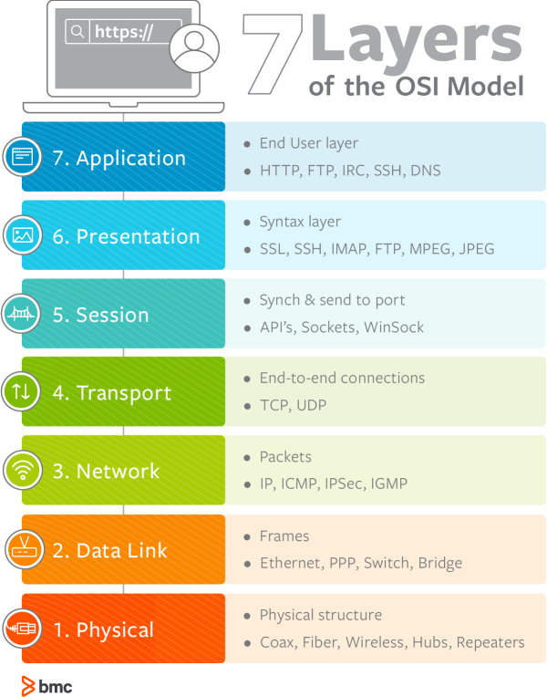
1. Physical
The lowest layer of the OSI model is concerned with data communication in the form of electrical, optic, or electromagnetic signals physically transmitting information between networking devices and infrastructure. The physical layer is responsible for the communication of unstructured raw data streams over a physical medium. It defines a range of aspects, including:
- Electrical, mechanical, and physical systems and networking devices that include specifications such as cable size, signal frequency, voltages, etc.
- Topologies such as Bus, Star, Ring, and Mesh
- Communication modes such as Simplex, Half Duplex, and Full Duplex
- Data transmission performance, such as Bit Rate and Bit Synchronization
- Modulation, switching, and interfacing with the physical transmission medium
- Common protocols including Wi-Fi, Ethernet, and others
- Hardware including networking devices, antennas, cables, modem, and intermediate devices such as repeaters and hubs
2. Data Link
The second layer of the OSI model concerns data transmission between the nodes within a network and manages the connections between physically connected devices such as switches. The raw data received from the physical layer is synchronized and packaged into data frames that contain the necessary protocols to route information between appropriate nodes. The data link layer is further divided into two sublayers:
- The Logical Link Control (LLC) sublayer is responsible for flow controls and error controls that ensure error-free and accurate data transmission between the network nodes.
- The Media Access Control (MAC) sublayer is responsible for managing access and permissions to transmit data between the network nodes. The data is transmitted sequentially and the layer expects acknowledgement for the encapsulated raw data sent between the nodes.
The third layer of the OSI model organizes and transmits data between multiple networks.
The network layer is responsible for routing the data via the best physical path based on a range of factors including network characteristics, best available path, traffic controls , congestion of data packets, and priority of service, among others. The network layer implements logical addressing for data packets to distinguish between the source and destination networks.
Other functions include encapsulation and fragmentation , congestion controls, and error handling. The outgoing data is divided into packets and incoming data is reassembled into information that is consumable at a higher application level. Network layer hardware includes routes, bridge routers, 3-layer switches, and protocols such as Internet (IPv4) Protocol version 4 and Internet Protocol version 6 (IPv6).
4. Transport
The fourth layer of the OSI model ensures complete and reliable delivery of data packets.
- The transport layer provides mechanisms such as error control, flow control, and congestion control to keep track of the data packets, check for errors and duplication, and resend the information that fails delivery. It involves the service-point addressing function to ensure that the packet is sent in response to a specific process (via a port address).
- Packet Segmentation and reassembly ensure that the data is divided and sequentially sent to the destination where it is rechecked for integrity and accuracy based on the receiving sequence.
Common protocols include the Transmission Control Protocol (TCP) for connection-oriented data transmission and User Datagram Protocol (UDP) for connectionless data transmission.
As the first of three layers that deal with the software level, the session layer manages sessions between servers to coordinate communication. Session refers to any interactive data exchange between two entities within a network. Common examples include HTTPS sessions that allow Internet users to visit and browse websites for a specific time period. The Session Layer is responsible for a range of functions including opening, closing, and re-establishing session activities, authentication and authorization of communication between specific apps and servers, identifying full-duplex or half-duplex operations, and synchronizing data streams.
Common Session Layer protocols include:
- Remote procedure call protocol (RPC)
- Point-to-Point Tunneling Protocol (PPTP)
- Session Control Protocol (SCP)
- Session Description Protocol (SDP), as described here
6. Presentation
The sixth layer of the OSI model converts data formats between applications and the networks. Responsibilities of the presentation layer include:
- Data conversion
- Character code translation
- Data compression
- Encryption and decryption
The presentation layer, also called the syntax layer, maps the semantics and syntax of the data such that the received information is consumable for every distinct network entity. For example, the data we transfer from our encryption-based communication app is formatted and encrypted at this layer before it is sent across the network.
At the receiving end, the data is decrypted and formatted into text or media information as originally intended. The presentation layer also serializes complex information into transportable formats. The data streams are then deserialized and reassembled into original object format at the destination.
7. Application
The application layer concerns the networking processes at the application level. This layer interacts directly with end-users to provide support for email, network data sharing, file transfers, and directory services, among other distributed information services. The upper most layer of the OSI model identifies networking entities to facilitate networking requests by end-user requests, determines resource availability, synchronizes communication, and manages application-specific networking requirements. The application layer also identifies constraints at the application level such as those associated with authentication, privacy, quality of service, networking devices, and data syntax.
Common application layer protocols include:
- File Transfer Protocol (FTP)
- Simple Mail Transfer Protocol (SMTP)
- Domain Name System (DNS)
The internet doesn’t welcome OSI
The OSI model is widely criticized for an inherent implementation complexity that renders networking operations inefficient and slow. The academic approach to developing the OSI protocol suite relied on replacing existing protocols across all communication layers with better alternatives.
This approach failed to gain traction in the industry; vendors had already invested significant resources in TCP/IP products and had to manage interoperability with the vast choices of protocols and specifications offered by the OSI model. Additionally, academia itself considered the OSI model as an invention politically inspired by the European telecommunication and U.S. government authorities.
The older TCP/IP architecture model had already itself in real-world network environments. It served as a solid foundation for the Internet–including all of the security , privacy, and performance-related challenges. Continued research and development, investments, and industry-wide adoption of the OSI model could have made today’s cyber world a different (and perhaps better) place, but the pragmatism of the TCP/IP model gave us the internet that prevails today.
Additional resources
Learn more with these resources:
- BMC IT Operations Blog
- IT Infrastructure Management: An Introduction
- IT Infrastructure Planning: Getting Started
- Network Engineer vs Network Administrator: Roles, Responsibilities, and Job Descriptions
- What Is a Virtual Network?
Original reference image:
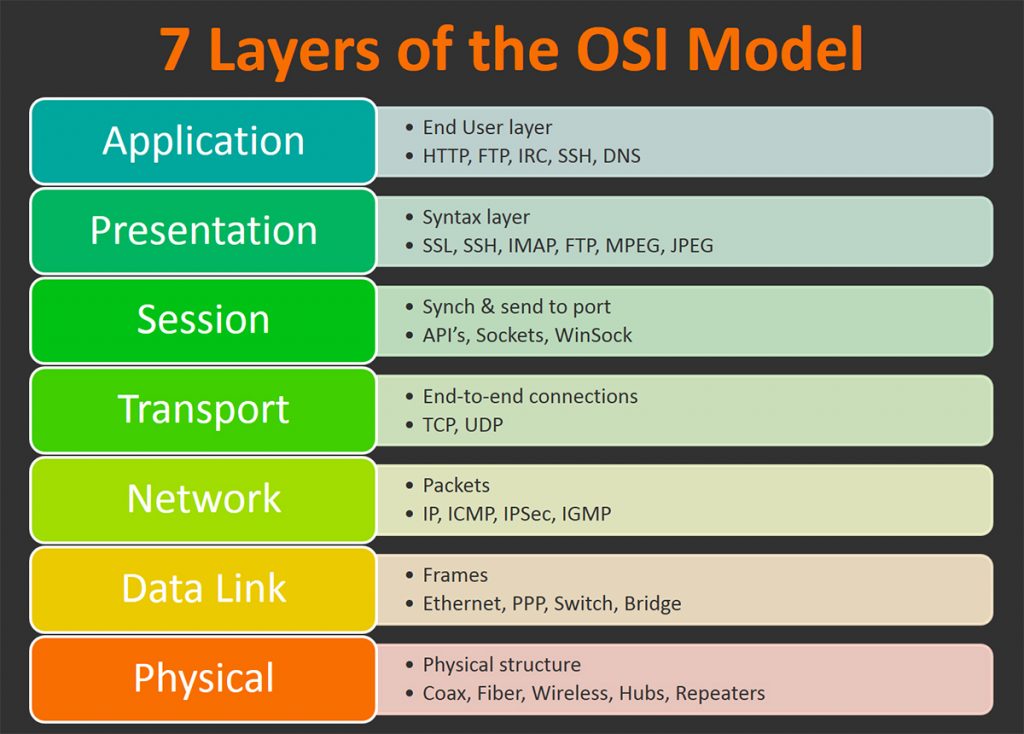
New strategies for modern service assurance
86% of global IT leaders in a recent IDG survey find it very, or extremely, challenging to optimize their IT resources to meet changing business demands.

These postings are my own and do not necessarily represent BMC's position, strategies, or opinion.
See an error or have a suggestion? Please let us know by emailing [email protected] .
Business, Faster than Humanly Possible
BMC works with 86% of the Forbes Global 50 and customers and partners around the world to create their future. With our history of innovation, industry-leading automation, operations, and service management solutions, combined with unmatched flexibility, we help organizations free up time and space to become an Autonomous Digital Enterprise that conquers the opportunities ahead. Learn more about BMC ›
You may also like

Top IT Operations Trends in 2022

Top DBA Shell Scripts for Monitoring the Database

How Data Center Cooling Works & Can Promote Sustainability

How To Build Better Virtualization Strategies

IT Operations Best Practices

Self-Service IT Thrives in the Clouds
About the author.
Muhammad Raza
Muhammad Raza is a Stockholm-based technology consultant working with leading startups and Fortune 500 firms on thought leadership branding projects across DevOps, Cloud, Security and IoT.
IMAGES
VIDEO
COMMENTS
Prerequisite : OSI Model. Introduction : Presentation Layer is the 6th layer in the Open System Interconnection (OSI) model. This layer is also known as Translation layer, as this layer serves as a data translator for the network. The data which this layer receives from the Application Layer is extracted and manipulated here as per the required ...
The presentation layer is the lowest layer at which application programmers consider data structure and presentation, instead of simply sending data in the form of datagrams or packets between hosts. This layer deals with issues of string representation - whether they use the Pascal method (an integer length field followed by the specified ...
In the seven-layer OSI model of computer networking, the presentation layer is layer 6 and serves as the data translator for the network. It is sometimes called the syntax layer. Description. Within the service layering semantics of the OSI network architecture, the presentation layer responds to service requests from the application layer and ...
Chloe Tucker. This article explains the Open Systems Interconnection (OSI) model and the 7 layers of networking, in plain English. The OSI model is a conceptual framework that is used to describe how a network functions. In plain English, the OSI model helped standardize the way computer systems send information to each other.
This article explains the seven layers in the OSI model, a network communication framework that simplifies complex network interactions into a structured format. ... Layer 6: Presentation Layer. Role: The Presentation Layer acts as a translator, converting data formats from the application layer into a network-compatible format and vice versa ...
The seven Open Systems Interconnection layers are the following. Layer 7. The application layer. The application layer enables the user -- human or software -- to interact with the application or network whenever the user elects to read messages, transfer files or perform other network-related tasks.
The presentation layer is located at Layer 6 of the OSI model. The tool that manages Hypertext Transfer Protocol ( HTTP) is an example of a program that loosely adheres to the presentation layer of OSI. Although it's technically considered an application-layer protocol per the TCP/IP model, HTTP includes presentation layer services within it.
The sixth layer of the OSI model is the Presentation layer. Applications running on the local system may or may not understand the format that is used to transmit the data over the network. The presentation layer works as a translator. When receiving data from the Application layer, it converts that data in such a format that can be sent over ...
The Presentation Layer is a crucial component of the OSI model, responsible for ensuring that data exchanged between systems is in a format that can be understood and used. By performing functions such as data translation, formatting, compression, and encryption, the Presentation Layer plays a vital role in maintaining data integrity ...
The transport layer, Layer 4, is responsible for being the go-between the abstract layers of the OSI model (Layers 7-5) and the concrete communication layers ... Layer 6: presentation layer. The presentation layer is primarily responsible for presenting data so that the recipient will understand the data.
7 Layers of the OSI Model. We will go through the different layers in detail below, but keep in mind that the upper layers (first 4) are about transport issues like the physical characteristics of the network and data transmission. The lower layers (last 3) are about application issues like data formatting and user interfacing.
The Open Systems Interconnection (OSI) model is a reference model from the International Organization for Standardization (ISO) that "provides a common basis for the coordination of standards development for the purpose of systems interconnection." In the OSI reference model, the communications between systems are split into seven different abstraction layers: Physical, Data Link, Network ...
The presentation layer in the OSI model has five main functions within the frame of presentation layer protocols. Character Code Translation A character code is a representation of text using a ...
OSI Model Explained. The Open Systems Interconnection (OSI) model is a framework that describes the functions of a networking system. The OSI model categorizes the computing functions of the different network components, outlining the rules and requirement needed to support the interoperability of the software and hardware that make up the ...
Prerequisite : OSI Model Introduction : Presentation Layer is the 6th layer in the Open System Interconnection (OSI) model. This layer is also known as Translation layer, as this layer serves as a data translator for the network. The data which this layer receives from the Application Layer is extracted and manipulated here as per the required form
The 7 layers of the OSI model. The layers are: Layer 1—Physical; Layer 2—Data Link; Layer 3—Network; Layer 4—Transport; Layer 5—Session; Layer 6—Presentation; Layer 7—Application. It ...
The Open Systems Interconnection (OSI) model is a conceptual framework that divides network communications functions into seven layers. Sending data over a network is complex because various hardware and software technologies must work cohesively across geographical and political boundaries. The OSI data model provides a universal language for ...
The Open Systems Interconnection (OSI) model defines a networking framework to implement protocols in layers, with control passed from one layer to the next. It is primarily used today as a teaching tool. It conceptually divides computer network architecture into 7 layers in a logical progression. The lower layers deal with electrical signals ...
Each OSI model layer is part of a seven-stage stack. Information descends and ascends the stack as data flows through networks. In theory, the stacks represent critical processes in data transmission. These stages could include encryption, packet creation, flow management, and presentation.
The presentation layer is the 6 th layer from the bottom in the OSI model. This layer presents the incoming data from the application layer of the sender machine to the receiver machine. It converts one format of data to another format of data if both sender and receiver understand different formats; hence this layer is also called the ...
In the OSI reference model, the communications between a computing system are split into seven different abstraction layers: Physical, Data Link, Network, Transport, Session, Presentation, and Application. Created at a time when network computing was in its infancy, the OSI was published in 1984 by the International Organization for ...
These groupings allow us to generally refer to OSI model function — software, Heart of OSI, hardware — without getting into the specific functions of each layer. Software layers The Application, Presentation, and Session layers (layers 7, 6, and 5) are collectively referred to as Software Layers of the model.
The 7 layers of the OSI model. This image illustrates the seven layers of the OSI model. Below, we'll briefly describe each layer, from bottom to top. 1. Physical. The lowest layer of the OSI model is concerned with data communication in the form of electrical, optic, or electromagnetic signals physically transmitting information between ...
The presentation layer is the sixth layer of the Open Systems Interconnection (OSI), model. In computer networking, the OSI model is a concept that describes the transmission of data from one computer to another. Each layer in the model is a packet of protocols, or procedures that govern data transmission, which allow the layer to execute ...
Bryeshia Cooper IT-640 February 28, 2021 DQ 2 The OSI model has seven layers. These layers are application, presentation, session, transport, network, data link, and physical. In an educational setting, the network layer is important. The network layer "controls the operation of the subnet, deciding which physical path the data should take ...
VU23213 Utilise basic network concepts and protocols required in Cyber security OSI model. 1. Which layer of the OSI model is responsible for establishing, maintaining, and terminating connections between devices? a) Application Layer b) Transport Layer c) Data Link Layer d) Session Layer Answer: d) Session Layer. 2.