Hall-Effect Current Sensors: Principles of Operation and Implementation Techniques
Ieee account.
- Change Username/Password
- Update Address

Purchase Details
- Payment Options
- Order History
- View Purchased Documents
Profile Information
- Communications Preferences
- Profession and Education
- Technical Interests
- US & Canada: +1 800 678 4333
- Worldwide: +1 732 981 0060
- Contact & Support
- About IEEE Xplore
- Accessibility
- Terms of Use
- Nondiscrimination Policy
- Privacy & Opting Out of Cookies
A not-for-profit organization, IEEE is the world's largest technical professional organization dedicated to advancing technology for the benefit of humanity. © Copyright 2024 IEEE - All rights reserved. Use of this web site signifies your agreement to the terms and conditions.

Hall effect instruments, evolution, implications, and future prospects
Electronic mail: [email protected]
Electronic mail: [email protected]
Electronic mail: [email protected]
- Article contents
- Figures & tables
- Supplementary Data
- Peer Review
- Reprints and Permissions
- Cite Icon Cite
- Search Site
Naman Goel , Aniket Babuta , Abhimanyu Kumar , Souvik Ganguli; Hall effect instruments, evolution, implications, and future prospects. Rev. Sci. Instrum. 1 July 2020; 91 (7): 071502. https://doi.org/10.1063/5.0009647
Download citation file:
- Ris (Zotero)
- Reference Manager
Since the revolution in solid state electronics, many innovative principles were investigated for a better and simpler design. Thus, Hall effect-based sensors and instruments gained importance. To employ this principle in several operating conditions and with different setups, several researchers contributed significantly over the decades, which ultimately led to the establishment of industries producing a wide range of Hall devices. The objective of this paper is to review the available configurations and current status of the Hall effect-based technologies. A detailed discussion is carried out on the various types of existing Hall-based devices, such as linear sensors, field-programmable sensors, switches, latches, speed and directional sensors, and vane sensors. The effect of materials and the influence of several undesired effects (such as offset voltage, temperature, noise, and drift) are also investigated. The compensation/reduction techniques are mentioned therein, and interested researchers are encouraged for the development of new techniques. This paper concludes with the discussion on the market scenario (such as electronics sector and automotive industry) and progression in current research on Hall devices while projecting some new research directions in this field.
Sign in via your Institution
Citing articles via, submit your article.

Sign up for alerts

- Online ISSN 1089-7623
- Print ISSN 0034-6748
- For Researchers
- For Librarians
- For Advertisers
- Our Publishing Partners
- Physics Today
- Conference Proceedings
- Special Topics
pubs.aip.org
- Privacy Policy
- Terms of Use
Connect with AIP Publishing
This feature is available to subscribers only.
Sign In or Create an Account
Temperature considerations on Hall Effect sensors current-related sensitivity behaviour
- Published: 15 October 2013
- Volume 77 , pages 355–364, ( 2013 )
Cite this article

- Maria-Alexandra Paun 1 nAff2 ,
- Jean-Michel Sallese 1 &
- Maher Kayal 1
667 Accesses
18 Citations
Explore all metrics
The present paper focuses on evaluating the temperature effects on Hall Effect sensors sensitivity behavior. To this purpose, an analysis of the factors affecting the sensors current-related sensitivity is performed, consisting of several pertinent considerations. An analytical investigation of the carrier concentration temperature dependence including the freeze-out effect influence was performed. This information was subsequently included in accurate prediction of the current-related sensitivity temperature behavior. For a specific CMOS integration process of the Hall sensors, a parabolic curve is obtained for the relative variation of the current-related sensitivity.
This is a preview of subscription content, log in via an institution to check access.
Access this article
Price includes VAT (Russian Federation)
Instant access to the full article PDF.
Rent this article via DeepDyve
Institutional subscriptions
Exploiting bi-modulated magnetic field and drive current modulation to achieve high-sensitivity Hall measurements on thermoelectric samples

Robustness, Reliability and Diagnostic Aspects in Sensors for Automotive Applications: The Magnetic Sensors Case

Sensitivity and Offset Voltage Testing in the Hall-Effect Sensors Made of Graphene
Ramsden, E. (2006). Hall-Effect sensors: Theory and applications (2nd ed.). Amsterdam: Elsevier.
Google Scholar
Manzin, A., Nabaei, V., & Kazakova, O. (2012). Modelling and optimization of submicron Hall sensors for the detection of superparamagnetic beads. Journal of Applied Physics , 111 (7), 07E513–07E513-3.
Osterberg, F. W., Rizzi, G., Gomez, Zardan, de la Torre, T., Stromberg, M., Stromme, M., et al. (2013). Measurements of Brownian relaxation of magnetic nanobeads using planar Hall effect bridge sensors. Biosensors & Bioelectronics, 40 (1), 147–152.
Article Google Scholar
Bolshakova, I., Vasilevskii, I., Viererbl, L., Duran, I., Kovalyova, N., Kovarik, K., et al. (2013). Prospects of using in-containing semiconductor materials in magnetic field sensors for thermonuclear reactor magnetic diagnostics. IEEE Transactions on Magnetics, 49 (1), 50–53.
Paun, M. A., Sallese, J. M., & Kayal, M. (2013). Comparative study on the performance of five different Hall Effect devices, Sensors , ISSN 1424–8220, 13 (2), 2093–2112.
Paun, M. A., Sallese, J. M., & Kayal, M. (2013). Hall effect sensors design, integration and behaviour analysis. Journal of Sensors and Actuator Networks, 2 (1), 85–97.
Paun, M. A. (2013). Hall cells offset analysis and modeling approaches , PhD thesis, EPFL, Switzerland.
Paun, M. A., Sallese, J. M., & Kayal, M. (2010). Geometry influence on Hall effect devices performance. UPB Scientific Bulletin, 72 (4), 257–271.
Paun, M. A., Sallese, J. M., & Kayal, M. (2011). Geometrical parameters influence on the Hall effect sensors offset and drift. In Proceedings of the 7th Conference on Ph.D. Research in Microelectronics and Electronics ( PRIME ), (pp. 145–148). Italy: IEEE.
Paun, M. A., Sallese, J. M., & Kayal, M. (2012). A specific parameters analysis of CMOS Hall effect sensors with various geometries. In Proceedings of the 19th International Conference on Mixed Design of Integrated Circuits and Systems ( MIXDES ), (pp. 335–339), Varsaw: IEEE.
Paun, M. A., Sallese, J. M., & Kayal, M. (2011). Hall effect sensors performance investigation using three-dimensional simulations. In Proceedings of the 18th International Conference on Mixed Design of Integrated Circuits and Systems ( MIXDES ), (pp. 450–455), Gliwice: IEEE.
Popovic, R. S. (2004). Hall effect devices (2nd ed.). Bristol, UK: Institute of Physics Publishing.
Book Google Scholar
Blanchard, H., Iseli, C. D., & Popovic, R. S. (1997). Compensation of the temperature-dependent offset drift of a Hall sensor. Sensors and Actuators A-Physical, 60 (1–3), 10–13.
Blanchard, H., & Popovic, R. S. (1999). On chip compensation of the temperature dependent offset drift of Hall sensors. In Proceeedings of the 10th International Conference on Solid - State Sensors and Actuators (Transducers’99 ), (pp. 598–601), Sendai, Japan.
Suzuki, K. (2010). Analysis of ion implantated profiles for accurate process/device simulation: Ion implantation profile database based on tail function. Fujitsu Scientific & Technical Journal, 46 (3), 307–317.
Xu, Y., & Pan, H.-B. (2011). An improved equivalent simulation model for CMOS integrated Hall plates. Sensors, 11 , 6284–6296.
Manic, D., Petr, J., & Popovic, R. S. (2000). Temperature cross-sensitivity of Hall plate in submicron CMOS technology. Sensors and Actuators A, 85 , 244–248.
Demierre, M. (2003). Improvements of CMOS Hall Microsystems and Applications for Absolute Angular Position Measurements , Ph.D. Thesis, Ecole Polytechnique Federale de Lausanne, Lausanne, Switzerland.
Sze, S. M., & Ng, K. K. (2007). Physics of semiconductor devices (3rd ed.). Hoboken, NJ: Wiley.
Dimitropoulos, P. D., Drljaca, P. M., Popovic, R. S., & Chatznikolaou, P. (2008). Horizontal Hall devices: A lumped circuit model for EDA simulators. Sensors and Actuators A, 145–146 , 161–175.
Ajbl, A., Pastre, M., & Kayal, M. (2013). A fully integrated Hall sensor microsystems for contactless current measurement. IEEE Sensors Journal, 13 (6), 2271–2278.
Paun, M. A., Sallese, J. M., & Kayal, M. (2013). A Circuit Model for CMOS Hall Cells Performance Evaluation including Temperature Effect, Advances in Condensed Matter Physic s, 2013 , Article ID 968647, 10p.
Download references
Acknowledgments
The first author, Maria-Alexandra Paun, wishes to thank the Swiss National Science Foundation (SNSF) from Switzerland for the promotion and encouragement of the scientific research of young doctors, respectively by providing the funding for her postdoctoral fellowship at Cambridge University.
Author information
Maria-Alexandra Paun
Present address: Department of Engineering, University of Cambridge, Cambridge, UK
Authors and Affiliations
STI-IEL-Electronics Laboratory, Ecole Polytechnique Fédérale de Lausanne (EPFL), Lausanne, Switzerland
Maria-Alexandra Paun, Jean-Michel Sallese & Maher Kayal
You can also search for this author in PubMed Google Scholar
Corresponding author
Correspondence to Maria-Alexandra Paun .
Rights and permissions
Reprints and permissions
About this article
Paun, MA., Sallese, JM. & Kayal, M. Temperature considerations on Hall Effect sensors current-related sensitivity behaviour. Analog Integr Circ Sig Process 77 , 355–364 (2013). https://doi.org/10.1007/s10470-013-0188-6
Download citation
Received : 13 May 2013
Revised : 15 September 2013
Accepted : 23 September 2013
Published : 15 October 2013
Issue Date : December 2013
DOI : https://doi.org/10.1007/s10470-013-0188-6
Share this article
Anyone you share the following link with will be able to read this content:
Sorry, a shareable link is not currently available for this article.
Provided by the Springer Nature SharedIt content-sharing initiative
- Hall Effect sensors
- Temperature behavior
- Freeze-out effect
- Current-related sensitivity
- Parabolic dependence
- Find a journal
- Publish with us
- Track your research

Detection techniques of biological and chemical Hall sensors

First published on 11th February 2021
Integrated magnetic Hall effect sensors have been widely used in people's daily life over the past decades, and still are gaining enormous attention from researchers to establish novel applications, especially in biochemistry and biomedical healthcare. This paper reviews, classifies, compares and concludes state-of-the-art integrated Hall magnetic sensors in terms of cost, power, area, performance and application. Current applications of the Hall sensors such as detecting magnetic nanoparticles (MNPs) labeled on biomolecule, monitoring blood pulse wave velocity, characterizing soft biological materials, controlling syringe injection rate and eye surgery by training systems, and assisting magnetic resonance imaging (MRI) will be discussed comprehensively and future applications and trends will be highlighted. This review paper will introduce Hall sensor's advantages such as simple design and technology of manufacturing, low cost, low power consumption, possibility of the miniaturizing, noninvasive and room temperature measurement, with respect to the other magnetic sensing systems and methods.

1 Introduction
The magnetoresistance effect was discovered by Thomson in 1856. It refers to the phenomenon that when a magnetic field is applied to an energized object under certain circumstances where the applied magnetic field is inconsistent with the internal magnetization direction of the object, the magnetic field will change the direction of the current, thereby changing the resistance value of the material. Magnetoresistive sensors show superior performance in sensitivity and signal-to-noise ratio, but they are expensive with CMOS manufacturing processes.
Today, magnetic sensors are the key elements in several fundamental studies as well as industrial applications. The demand of biomedicine expands the application scenarios of Hall sensors, benefiting from their low price. Various magnetic sensing devices such as superconducting quantum interference devices (SQUIDs), 5–8 magnetic resonance imaging (MRI), 9–11 nuclear magnetic resonance (NMR) 12,13 have been utilized in these areas. These devices exhibit high sensitivity, however, their large physical size and expensive price limit their popularity. 14,15 If required a momentary and enormous screening tests for diseases like Ebola and SARS, traditional bulky devices are not suitable. 16 Considering advantages of magnetic sensing technologies, the miniaturized systems bring down the size and cost because of benefits from integrated thin-film magnetic sensors like Hall sensors 17–22 giant magnetoresistance (GMR) 23,24,24–29 and tunneling magnetoresistive (TMR) 30–32 and fluxgate sensors, 33,34 etc. Although the GMR and fluxgate sensors can be integrated with sensor readout circuitry to significantly reduce system size 35–37 and they are more sensitive than Hall sensors to detect the weak magnetic field, the used materials for fabrication are relatively not common in the foundry, which causes high cost for the GMR, TMR and fluxgate sensors. 14,15,38–40 In addition, some biomedical applications do not need such a high sensitivity sensor. 16 At present, the Hall sensors are the most widely used magnetic sensor in the market, which exhibit small physical size, low-cost and is compatible with standard CMOS technology. 41–47
Fig. 1(a) demonstrates the basic concept and application scenarios of Hall sensor, while Fig. 1(b) shows the number of publications in magnetic sensors and the Hall sensors used in biomedical applications during the last 20 years (from 2000 to 2020). It is obviously noted that the researches of Hall sensors are significantly increased by years, similarly with trend of the total magnetic sensors.
We collected, classified, compared and concluded the integrated Hall sensors used in biomedical applications in recent years (from 2014 to 2020), including detection of DNA, protein and blood using MNPs as the bio-labels, monitor of blood pulse wave velocity, characterization of soft biological materials, control of syringe injection rate and eye surgery by training systems, and MRI assistance. The overview of Hall applications is demonstrated in Fig. 2 . The Hall sensor is an innovative tool for detecting MNPs as an applicable and challenging task. 48–54 This paper reviews the Hall sensor applications and introduces them specifically. Since the available commercial Hall sensors are not commonly suitable from sensitivity, size, shape and compatibility points of view for the MNP detection, 16,49,55–59 we focus on the homemade Hall sensors developed by different research groups.
2 Hall sensor for bio-chemical detection
Recently, Kuo et al. implemented the Hall sensor to detect the concentration of Tumor necrosis factor-α (TNF-α, related to anti-tumor) and N-terminal pro-brain natriuretic peptide (NT-proBNP, related to heart failure) by using a label based on 1.5 μm MNPs. 16 By referring to Fig. 4(a and b) , in vitro tumor necrosis factor-α (TNF-α) and NT-proBNP tests were performed. The concentrations of TNF-α and NT-proBNP solutions range from 0.8 pg mL −1 to 800 ng mL −1 . These can be detected by the Hall sensor from the change of Hall voltages. The warning threshold can be preset so that when the concentration exceeds the preset value, the user will be warned for further inspection. An 8 × 8 Hall device array is adopted and fabricated using the 0.35 μm CMOS technology with die size of 8.89 mm 2 . It has achieved 0.039 V/V/T sensitivity. The chip is based on a system on chip structure in which a microcontroller unit can control the detection process automatically. Generally, the detection process can be divided into four steps, as shown in Fig. 4(c) : (1) filtering target (TNF-α or NT-proBNP) into a chip reservoir to divide targets and blood cells through an anodic aluminium oxide; (2) pumping bubbles induced by electrolytic water to move the target into a sensing area; (3) flushing unbound MNPs in the sensor area by inducing a magnetic field from a chip inner coil; (4) starting a detection action. An alarm LED will illuminate when the concentration of bound MNPs exceeds the static setpoint. There is a log relationship between the number of MNPs and the output voltage generated by an analog front-end of a single Hall device.
In addition, Gambini has implemented the Hall sensor to detect the concentration of Human Serum Albumin (HSA). 57 The normalized chip output is changed with the concentration of HAS, as shown in Fig. 5(a) . A 64 × 160 Hall-device arrays is adopted and fabricated using the 0.18 μm CMOS technology with a die size of 17.85 mm 2 . Its sensitivity could reach 0.029 V/V/T. However, conventional methods have a low 1% signal-to-baseline ratio, which means 1% fluctuation of the baseline can lead to a considerable signal error. To resolve this problem, they considered the dynamic property of MNPs to measure the magnetic field of magnetized MNPs in their relaxation time, as shown in Fig. 5(b and c) . In theory, the baseline of the magnetic field should be zero in the relaxation measurement. Therefore, the signal-to-baseline ratio is infinite and their sensor achieves a ratio larger than 1. In particular, compared with their previous design, adopting a single channel with the readout time 64 s in 2012, 76 the group implements a parallel readout channel where the readout time is only 8 s. Finally, since the MNPs have small physical size and magnetic field signal, it is vulnerable to environmental noise, earth's magnetic field and unsteady baseline etc. Therefore, this group also introduced a specific circuit design scheme to obtain the accuracy signal of the MNPs. M450 (4.5 μm), M280 (2.8 μm), M1 (1 μm) are utilized as a verification of the sensor function, as shown in Fig. 5(d) . There is approximately a linear relationship between the number of beads and the sensor output.
Bhalla et al. have used the Hall sensor to detect the concentration of Adiponectin (related to fat) using 10 nm MNPs as a label. 55 The sensor is fabricated by using the 0.35 μm BioMEMS technology and has the sensitivity of 26 V/A/T. The phase shift of the sensor output signals between inductor 1 (without MNPs) and inductor 2 (with MNPs) indicated a linear relationship with MNPs concentration on the microfluid platform, as shown in Fig. 6(a and b) . The microfluidic platform has eight chambers in total, five of which are used for loading reagents and the others for washing reagents, reaction and waste chambers. A system structure of the microfluidic platform experiment is demonstrated in Fig. 6(c) . The immunoassays process takes 2 hours and 15 minutes, including incubation bounding MNPs with the antibody, washing and detection etc.
Kim et al. have built a microfluidic platform where a planar Hall magnetoresistive (PHR) sensor is implemented to investigate the property of MNPs, as show in Fig. 7(a) . 77 Schematic drawing of on chip magnetometer, in which the channels (F1–F4) represented in purple color are flow channels for the generation of ferrofluid droplets, and the channels (C1–C4) represented in red color are control channels (valves) for the operation of ferrofluid droplet oscillation. A linear relationship is obtained between the concentration of MNPs and magnetization measured indirectly by the PHR sensor in ferrofluid, as shown in Fig. 7(b) . The sensor is fabricated on a silicon wafer using a NiFe/Cu/IrMn trilayer structure with an absolute sensitivity of 0.085 V/V/T. A Maxwell software has been carried out to simulate the magnetic field in a droplet sensing area and optimize the length of the droplet in the microfluidic platform, as shown in Fig. 7(c) . It is noted that the critical length to have apparent signals is 70 μm. The output signal of the PHR sensor is in corresponds to different positions of droplets and also different magnetic fields. 78,79
In more recent works, Loan et al. have investigated the processing technology for ultraclean graphene film without the photoresist polymethyl methacrylate (PMMA) residue. 83 A new method for detecting DNA is employed without using MNPs. The Hall devices were designed based on the ultraclean graphene and the PMMA residue-based graphene respectively. The sensor sensitivity based on the ultraclean graphene is about 5 times larger than the one based on the PMMA residue. A DNA experiment was carried out on the ultraclean graphene-based sensor surface. Finally, the carrier concentration, carrier mobility and sheet resistance of Hall device are related to the concentration of DNAs. Their relationships are shown in Fig. 9(a–d) .
Except for the detections of DNA, protein and blood outside the human body, the Hall sensor and MNPs are also a versatile device for disease detections inside of the human body. For instance, Ookubo et al. and Kuwahata et al. have implemented a Hall sensor (NHE520) to detect magnetic fluid containing MNPs for sentinel lymph node biopsy. 84,85
3 Performance development
As the low-cost characteristic and CMOS compatibility, Hall-effect sensors were commonly used in the automation field. Researchers have considered magnetic sensor for novel applications in the detection of MNPs. The diameter of MNPs is very small, usually, only a micrometer or nanometer leading to few molecule electric current and weak magnetic. III–V semiconductor Hall devices are frequently utilized in the early exploration due to their superior characteristic for the weak magnetic field. 14,56,61–63,65,66,78,87,88 For example, InSb Hall device can detect the weak magnetic field as low as picoTesla, 89,90 and GaAs sensor can detect nanotesla easily. InAs is considered mostly in the early period because of its ultra-high mobility up to 2.5 × 10 4 cm 2 V −1 s −1 (silicon is 1450 cm 2 V −1 s −1 ) which lead to high sensitivity of Hall-effect device. InSb and InGaAs are also common materials used in the early exploration. However, comparing to silicon Hall-device, all of them hardly have the processing technology to integrate Hall-devices with complex circuits. Mature CMOS bio-Hall integrated sensors have emerged in recent years. The performance and the characteristics of Hall sensor are presented in Table 2 .
Besse et al. implemented a high-sensitivity silicon CMOS Hall sensor to detect magnetic microbeads with a diameter of 2.8 μm. Two detection methods using the superparamagnetic properties of magnetic beads were tested experimentally, and their performances were compared. Their work is based on the use of silicon Hall sensors and dense arrays of CMOS electronics, opening the way for low-cost microsystems for biochemical applications. Liu et al. designed a CMOS Hall sensor chip specifically for characterizing and detecting magnetic nanoparticles. Its time resolution is three orders of magnitude higher than existing solutions based on superconducting quantum interference devices and fluxgate sensors. Bhalla et al. used TSMC's 0.35 μm process to design and manufacture Hall sensors that can be used to detect specific proteins contained in 10 nm magnetic beads. It can achieve a rapid detection in 2 hours and 15 minutes while ensuring accuracy, which provides convenience for handling emergencies. Kuo et al. utilized MCU(Micro control unit) to complete a fully automated immunoassay laboratory, and the main sensor used is a Hall magnetic sensor made of 0.35 μm CMOS process. The Hall sensor designed by Gambini et al. under the 0.18 μm CMOS process contains 8 × 8 Hall devices. Compared with a single Hall device, this method's measurement sensitivity of to the magnetic beads is improved by more than 50 times. Another advantage is that the combination of multiple Hall devices can minimize the misalignment caused by process factors.
With the development of microelectronic technology, the sensitivity, size, and power consumption of Hall sensors are constantly optimized. The preliminary results in the field of biochemistry have attracted some people's attention to Hall magnetic sensors. There will be more scientific researchers to explore the potential of Hall magnetic sensors. Low price, high accuracy, multi-function, and easy to carry testing equipment are the mainstream research directions.
4 Biochemistry applications and future directions
4.1 application i: blood pulse wave velocity detection, 4.2 application ii: training system for syringe and eye surgery, 4.3 application iii: characterizing soft biological material, 4.4 application iv: assisting mri, 4.5 other applications, 5 conclusion, conflicts of interest, acknowledgements, notes and references.
- C. Wouters, V. Vranković, C. Rössler, S. Sidorov, K. Ensslin, W. Wegscheider and C. Hierold, Sens. Actuators, A , 2016, 237 , 62–71 CrossRef CAS .
- C. Schott, R. Racz, F. Betschart and R. S. Popovic, IEEE SENSORS Conference , 2002, pp. 911–915 Search PubMed .
- T. Kaufmann, D. Kopp, M. Kunzelmann, P. Ruther and O. Paul, IEEE SENSORS Conference , 2011, pp. 440–443 Search PubMed .
- H. Heidari, S. Zuo, A. Krasoulis and K. Nazarpour, 2018 40th Annual International Conference of the IEEE Engineering in Medicine and Biology Society (EMBC) , 2018, pp. 2116–2119 Search PubMed .
- K. Enpuku, K. Inoue, K. Soejima, K. Yoshinaga, H. Kuma and N. Hamasaki, IEEE Trans. Appl. Supercond. , 2005, 15 , 660–663 CrossRef CAS .
- C. Tamanaha, S. Mulvaney, J. Rife and L. Whitman, Biosens. Bioelectron. , 2008, 24 , 1–13 CrossRef CAS .
- A. Tsukamoto, K. Saitoh, D. Suzuki, N. Sugita, Y. Seki, A. Kandori, K. Tsukada, Y. Sugiura, S. Hamaoka, H. Kuma, N. Hamasaki and K. Enpuku, IEEE Trans. Appl. Supercond. , 2005, 15 , 656–659 CrossRef CAS .
- J. Lenz and S. Edelstein, IEEE Sens. J. , 2006, 6 , 631–649 Search PubMed .
- S. I. Farrag, IEEE Conference on Biomedical Engineering and Sciences (IECBES) , 2014, pp. 612–617 Search PubMed .
- M. E. Ladd, L. Umutlu, S. Maderwald, S. Kinner, S. Orzada, K. Nassenstein, I. Brote, H. Quick, L. Schaefer, S. Ladd, G. Antoch, O. Kraff, A. Bitz and T. Lauenstein, IEEE Int. Symposium on Biomedical Imaging: From Nano to Macro , 2010, pp. 572–572 Search PubMed .
- S. Yamaguchi-Sekino, M. Sekino and T. Nakai, IEEE Trans. Magn. , 2015, 51 , 1–4 Search PubMed .
- H. Lee, E. Sun, D. Ham and R. Weissleder, Nat. Med. , 2008, 14 , 869–874 CrossRef CAS .
- N. Sun, T. Yoon, H. Lee, W. Andress, R. Weissleder and D. Ham, IEEE J. Solid-State Circuits , 2011, 46 , 342–352 Search PubMed .
- J. Llandro, J. Palfreyman, A. Ionescu and C. Barnes, Med. Biol. Eng. Comput. , 2010, 48 , 977–998 CrossRef CAS .
- M. Lucas and E. Riedo, Rev. Sci. Instrum. , 2012, 83 , 061101 CrossRef .
- P.-H. Kuo, J.-C. Kuo, H.-T. Hsueh, J.-Y. Hsieh, Y.-C. Huang, T. Wang, Y.-H. Lin, C.-T. Lin, Y.-J. Yang and S.-S. Lu, IEEE Transactions on Biomedical Circuits and Systems , 2015, 9 , 790–800 Search PubMed .
- D. A. Hall, R. S. Gaster, S. J. Osterfeld, K. Makinwa, S. X. Wang and B. Murmann, 2011 Symposium on VLSI Circuits-Digest of Technical Papers , 2011, pp. 174–175 Search PubMed .
- W. Lee, S. Joo, S. U. Kim, K. Rhie, J. Hong, K.-H. Shin and K. H. Kim, Appl. Phys. Lett. , 2009, 94 , 153903 CrossRef .
- P. Liu, K. Skucha, M. Megens and B. Boser, IEEE Trans. Magn. , 2011, 47 , 3449–3451 Search PubMed .
- A. Sandhu, H. Sanbonsugi, I. Shibasaki, M. Abe and H. Handa, Jpn. J. Appl. Phys. , 2004, 43 , L868 CrossRef CAS .
- K. Skucha, P. Liu, M. Megens, J. Kim and B. Boser, 2011, 16th International Solid-State Sensors, Actuators and Microsystems Conference , 2011, pp. 1833–1836 Search PubMed .
- H. Heidari, U. Gatti and F. Maloberti, 11th Conference on Ph. D. Research in Microelectronics and Electronics (PRIME) , 2015, pp. 330–333 Search PubMed .
- Z. Yin, E. Bonizzoni and H. Heidari, IEEE Journal of Electromagnetics, RF and Microwaves in Medicine and Biology , 2018, 2 , 179–185 Search PubMed .
- I. Ennen, D. Kappe, T. Rempel, C. Glenske and A. Hütten, Sensors , 2016, 16 , 904 CrossRef .
- D. R. Baselt, G. U. Lee, M. Natesan, S. W. Metzger, P. E. Sheehan and R. J. Colton, Biosens. Bioelectron. , 1998, 13 , 731–739 CrossRef CAS .
- T. Costa, F. A. Cardoso, J. Germano, P. P. Freitas and M. S. Piedade, IEEE Transactions on Biomedical Circuits and Systems , 2017, 11 , 988–1000 Search PubMed .
- D. Hall, R. Gaster, T. Lin, S. Osterfeld, S. Han, B. Murmann and S. Wang, Biosens. Bioelectron. , 2010, 25 , 2051–2057 CrossRef CAS .
- G. Rizzi, J.-R. Lee, P. Guldberg, M. Dufva, S. X. Wang and M. F. Hansen, Biosens. Bioelectron. , 2017, 93 , 155–160 CrossRef CAS .
- J. Xu, Q. Li, W. Zong, Y. Zhang and S. Li, J. Magn. Magn. Mater. , 2016, 417 , 25–29 CrossRef CAS .
- S. Zuo, K. Nazarpour and H. Heidari, IEEE Electron Device Lett. , 2018, 39 , 1784–1787 CAS .
- A. Tanwear, X. Liang, Y. Liu, A. Vuckovic, R. Ghannam, T. Böhnert, E. Paz, P. P. Freitas, R. Ferreira and H. Heidari, IEEE Transactions on Biomedical Circuits and Systems , 2020, 14 , 1299–1310 Search PubMed .
- S. Zuo, H. Heidari, D. Farina and K. Nazarpour, Adv. Mater. Technol. , 2020, 5 , 2000185 CrossRef .
- P. M. Drljača, P. Kejik, F. Vincent, D. Piguet, F. Gueissaz and R. S. Popović, Sens. Actuators, A , 2004, 110 , 236–241 CrossRef .
- C.-C. Lu, W.-S. Huang, Y.-T. Liu and J.-T. Jeng, IEEE Trans. Magn. , 2011, 47 , 3752–3755 Search PubMed .
- J. Nordling, R. L. Millen, H. A. Bullen, M. D. Porter, M. Tondra and M. C. Granger, Anal. Chem. , 2008, 80 , 7930–7939 CrossRef CAS .
- A. Weddemann, I. Ennen, A. Regtmeier, C. Albon, A. Wolff, K. Eckstädt, N. Mill, M. K.-H. Peter, J. Mattay and C. Plattner, et al. , Beilstein J. Nanotechnol. , 2010, 1 , 75–93 CrossRef CAS .
- A. Bernieri, G. Betta, L. Ferrigno and M. Laracca, IEEE Sens. J. , 2013, 13 , 4513–4521 Search PubMed .
- J. Li, X. Zhang, J. Shi, H. Heidari and Y. Wang, IEEE Sens. J. , 2019, 19 , 11819–11827 Search PubMed .
- H. Heidari and V. Nabaei, in Magnetic Sensors Based on Hall Effect , John Wiley & Sons, Ltd, 2019, ch. 2, pp. 33–56 Search PubMed .
- V. Nabaei, R. Chandrawati and H. Heidari, Biosens. Bioelectron. , 2018, 103 , 69–86 CrossRef CAS .
- E. Ramsden, Hall-effect sensors: theory and application , Elsevier, 2011 Search PubMed .
- A. Hassibi, S. Zahedi, R. Navid, R. W. Dutton and T. H. Lee, J. Appl. Phys. , 2005, 97 , 084701 CrossRef .
- H. Heidari, E. Bonizzoni, U. Gatti and F. Maloberti, 2014 IEEE International Symposium on Circuits and Systems (ISCAS) , 2014, pp. 678–681 Search PubMed .
- H. Heidari, U. Gatti, E. Bonizzoni and F. Maloberti, Proceedings of the 2013 9th Conference on Ph. D. Research in Microelectronics and Electronics (PRIME) , 2013, pp. 325–328 Search PubMed .
- H. Heidari, E. Bonizzoni, U. Gatti and F. Maloberti, IEEE Transactions on Circuits and Systems I: Regular Papers , 2015, 62 , 1270–1278 Search PubMed .
- H. Heidari, E. Bonizzoni, U. Gatti, F. Maloberti and R. Dahiya, IEEE Sens. J. , 2016, 16 , 8736–8743 CAS .
- R. Popović, Sens. Actuators , 1989, 17 , 39–53 CrossRef .
- A. Bilotti, G. Monreal and R. Vig, IEEE J. Solid-State Circuits , 1997, 32 , 829–836 CrossRef .
- P.-A. Besse, G. Boero, M. Demierre, V. Pott and R. Popovic, Appl. Phys. Lett. , 2002, 80 , 4199–4201 CrossRef CAS .
- W. de Jager and G. T. Rijkers, Methods , 2006, 38 , 294–303 CrossRef CAS .
- F. Conzuelo, M. Gamella, S. Campuzano, A. J. Reviejo and J. M. Pingarrón, Anal. Chim. Acta , 2012, 737 , 29–36 CrossRef CAS .
- W.-Y. Chung, A. A. Silverio, R. F. Ramezani, J.-Y. Lai and A. A. Silverio, IEEE Region 10 Conference - TENCON , 2017, pp. 1593–1597 Search PubMed .
- C. Menolfi and Q. Huang, IEEE J. Solid-State Circuits , 1997, 32 , 968–976 CrossRef .
- S. M. Dadfar, K. Roemhild, N. I. Drude, S. von Stillfried, R. Knüchel, F. Kiessling and T. Lammers, Adv. Drug Delivery Rev. , 2019, 138 , 302–325 CrossRef CAS .
- N. Bhalla, D. W. Y. Chung, Y.-J. Chang, K. J. S. Uy, Y. Y. Ye, T.-Y. Chin, H. C. Yang and D. G. Pijanowska, Micromachines , 2013, 4 , 257–271 CrossRef .
- G. Mihajlović, P. Xiong, S. von Molnár, K. Ohtani, H. Ohno, M. Field and G. J. Sullivan, Appl. Phys. Lett. , 2005, 87 , 112502 CrossRef .
- S. Gambini, K. Skucha, P. P. Liu, J. Kim and R. Krigel, IEEE J. Solid-State Circuits , 2012, 48 , 302–317 Search PubMed .
- T. Ishikawa and S. Tanaka, 2017 19th International Conference on Solid-State Sensors, Actuators and Microsystems (TRANSDUCERS) , 2017, pp. 1612–1615 Search PubMed .
- B. Cao, K. Wang, H. Xu, Q. Qin, J. Yang, W. Zheng, Q. Jin and D. Cui, Sens. Actuators, A , 2020, 112130 CrossRef CAS .
- D. Issadore, Y. Park, H. Shao, C. Min, K. Lee, M. Liong, R. Weissleder and H. Lee, Lab Chip , 2014, 14 , 2385–2397 RSC .
- O. Kazakova, J. Gallop, G. Perkins and L. Cohen, Appl. Phys. Lett. , 2007, 90 , 162502 CrossRef .
- P. Manandhar, K.-S. Chen, K. Aledealat, G. Mihajlović, C. S. Yun, M. Field, G. J. Sullivan, G. F. Strouse, P. B. Chase and S. von Molnár, et al. , Nanotechnology , 2009, 20 , 355501 CrossRef .
- G. Mihajlović, K. Aledealat, P. Xiong, S. Von Molnar, M. Field and G. J. Sullivan, Appl. Phys. Lett. , 2007, 91 , 172518 CrossRef .
- M. Nikitin, M. Torno, H. Chen, A. Rosengart and P. Nikitin, J. Appl. Phys. , 2008, 103 , 07A304 CrossRef .
- J. B. Haun, N. K. Devaraj, S. A. Hilderbrand, H. Lee and R. Weissleder, Nat. Nanotechnol. , 2010, 5 , 660–665 CrossRef CAS .
- G. Landry, M. Miller, B. Bennett, M. Johnson and V. Smolyaninova, Appl. Phys. Lett. , 2004, 85 , 4693–4695 CrossRef CAS .
- O. Florescu, K. Wang, P. Au, J. Tang, E. Harris, P. R. Beatty and B. E. Boser, J. Appl. Phys. , 2010, 107 , 054702 CrossRef .
- J.-C. Kuo, P.-H. Kuo, H.-T. Hsueh, C.-W. Ma, C.-T. Lin, S.-S. Lu and Y.-J. Yang, 2014 IEEE 27th International Conference on Micro Electro Mechanical Systems (MEMS) , 2014, pp. 809–812 Search PubMed .
- O. Florescu, M. Mattmann and B. Boser, Fully integrated detection of single magnetic beads in complementary metal-oxide-semiconductor , 2008 Search PubMed .
- J. Kaur, K. V. Singh, A. H. Schmid, G. C. Varshney, C. R. Suri and M. Raje, Biosens. Bioelectron. , 2004, 20 , 284–293 CrossRef CAS .
- K. Skucha, S. Gambini, P. Liu, M. Megens, J. Kim and B. Boser, IEEE ASME J. Microelectromech. Syst. , 2013, 22 , 1327–1338 CAS .
- Y. Zheng, N. Shang, P. S. Haddad and M. Sawan, IEEE transactions on biomedical circuits and systems , 2015, 10 , 477–486 Search PubMed .
- J. Mok, M. N. Mindrinos, R. W. Davis and M. Javanmard, Proc. Natl. Acad. Sci. U.S.A. , 2014, 111 , 2110–2115 CrossRef CAS .
- G. Proczek, A.-L. Gassner, J.-M. Busnel and H. H. Girault, Anal. Bioanal. Chem. , 2012, 402 , 2645–2653 CrossRef CAS .
- P. P. Liu, K. Skucha, Y. Duan, M. Megens, J. Kim, I. I. Izyumin, S. Gambini and B. Boser, IEEE J. Solid-State Circuits , 2012, 47 , 1056–1064 Search PubMed .
- K. W. Kim, V. Reddy, S. R. Torati, X. H. Hu, A. Sandhu and C. G. Kim, Lab Chip , 2015, 15 , 696–703 RSC .
- L. Di Michele, C. Shelly, P. de Marco, P. See, D. Cox and O. Kazakova, J. Appl. Phys. , 2011, 110 , 063916 CrossRef .
- H. Wang, Y. Chen, A. Hassibi, A. Scherer and A. Hajimiri, 2009 IEEE International Solid-State Circuits Conference-Digest of Technical Papers , 2009, pp. 438–439 Search PubMed .
- F. W. Østerberg, G. Rizzi, T. Z. G. de la Torre, M. Strömberg, M. Strømme, P. Svedlindh and M. Hansen, Biosens. Bioelectron. , 2013, 40 , 147–152 CrossRef .
- A. Henriksen, B. T. Dalslet, D. Skieller, K. Lee, F. Okkels and M. F. Hansen, Appl. Phys. Lett. , 2010, 97 , 013507 CrossRef .
- A. Persson, R. S. Bejhed, H. Nguyen, K. Gunnarsson, B. T. Dalslet, F. W. Oesterberg, M. F. Hansen and P. Svedlindh, Sens. Actuators, A , 2011, 171 , 212–218 CrossRef CAS .
- P. T. K. Loan, D. Wu, C. Ye, X. Li, V. T. Tra, Q. Wei, L. Fu, A. Yu, L.-J. Li and C.-T. Lin, Biosens. Bioelectron. , 2018, 99 , 85–91 CrossRef CAS .
- T. Ookubo, Y. Inoue, D. Kim, H. Ohsaki, Y. Mashiko, M. Kusakabe and M. Sekino, Electron. Commun. Jpn. , 2016, 99 , 13–21 CrossRef .
- A. Kuwahata, S. Chikaki, A. Ergin, M. Kaneko, M. Kusakabe and M. Sekino, AIP Adv. , 2017, 7 , 056720 CrossRef .
- P. Ripka and M. Janosek, IEEE Sens. J. , 2010, 10 , 1108–1116 Search PubMed .
- A. Sandhu, Y. Kumagai, A. Lapicki, S. Sakamoto, M. Abe and H. Handa, Biosens. Bioelectron. , 2007, 22 , 2115–2120 CrossRef CAS .
- H. Heidari and V. Nabaei, Magnetic Sensors for Biomedical Applications , John Wiley & Sons, 2019 Search PubMed .
- P. Ripka and M. Janosek, IEEE SENSORS Conference , 2008, pp. 1–4 Search PubMed .
- J. H. Kratzer, Magneto-optic properties of II-VI semiconductor quantum dots , Rensselaer Polytechnic Institute, 2005 Search PubMed .
- D. Accoto, M. Rossini, S. Valentini and I. Portaccio, IEEE Sens. J. , 2018, 18 , 3564–3571 Search PubMed .
- P. Nabeel, J. Joseph and M. Sivaprakasam, 36th Annual Int. Conference of the IEEE Engineering in Medicine and Biology Society , 2014, pp. 1953–1956 Search PubMed .
- P. Nabeel, J. Joseph and M. Sivaprakasam, IEEE transactions on biomedical circuits and systems , 2017, 11 , 1065–1076 Search PubMed .
- D.-H. Nam, W.-B. Lee, Y.-S. Hong and S.-S. Lee, Sensors , 2013, 13 , 4714–4723 CrossRef .
- K.-H. Kim and S.-S. Lee, New J. Phys , 2013, 63 , 1135–1139 Search PubMed .
- D.-H. Lee, Y.-S. Hong and S.-S. Lee, J. Korean Magn. Soc. , 2013, 23 , 135–143 CrossRef .
- B. Mukherjee, B. George and M. Sivaprakasam, 2013 35th Annual International Conference of the IEEE Engineering in Medicine and Biology Society (EMBC) , 2013, pp. 4734–4737 Search PubMed .
- B. Mukherjee, B. George and M. Sivaprakasam, IEEE Trans. Instrum. Meas. , 2014, 63 , 1153–1162 Search PubMed .
- K. Borvorntanajanya and J. Suthakorn, 2018 IEEE International Conference on Robotics and Automation (ICRA) , 2018, pp. 1–6 Search PubMed .
- G. Chatzipirpiridis, P. Erne, O. Ergeneman, S. Pané and B. J. Nelson, 37th Annual International Conference of the IEEE Engineering in Medicine and Biology Society (EMBC) , 2015, pp. 7970–7973 Search PubMed .
- D. S. Chathuranga, Z. Wang, Y. Noh, T. Nanayakkara and S. Hirai, 37th Annual Int. Conference of the IEEE Engineering in Medicine and Biology Society (EMBC) , 2015, pp. 5521–5524 Search PubMed .
- K. Singal, R. Rajamani, M. Ahmadi, A. S. Sezen and J. E. Bechtold, IEEE Trans. Biomed. Eng. , 2014, 62 , 426–437 Search PubMed .
- D. E. Backman, B. L. LeSavage and J. Y. Wong, J. Biomech. , 2017, 51 , 118–122 CrossRef .
- G. Chatzipirpiridis, S. Gervasoni, F. Berlinger, O. Ergeneman, S. Pané and B. Nelson et al. , Int. Conference on Solid-State Sensors, Actuators and Microsystems (TRANSDUCERS) , 2015, pp. 1727–1730 Search PubMed .
- J.-B. Schell, L. Cuvillon, D. Gounot, E. Breton, J.-B. Kammerer, L. Hébrard and M. de Mathelin, SENSORS, 2013 IEEE , 2013, pp. 1–4 Search PubMed .
- H. Fan, S. Li, V. Nabaei, Q. Feng and H. Heidari, IEEE Sens. J. , 2020, 20 , 9919–9927 Search PubMed .
- H. Fan, S. Li, Y. Cen, Q. Feng and H. Heidari, IEEE 63rd Int. Midwest Symposium on Circuits and Systems (MWSCAS) , 2020, pp. 893–896 Search PubMed .
- S. Yamaguchi-Sekino, T. Nakai, S. Imai, S. Izawa and T. Okuno, Bioelectromagnetics , 2014, 35 , 70–75 CrossRef .
- A. Delmas, L. Belguerras, N. Weber, F. Odille, C. Pasquier, J. Felblinger and P.-A. Vuissoz, Bioelectromagnetics , 2018, 39 , 108–119 CrossRef CAS .
- A. Caballero-Ruiz, L. I. Garcia-Beltran, L. Ruiz-Huerta and F. Heredia-Lopez, Int. Conference on Mechatronics, Electronics and Automotive Engineering , 2014, pp. 168–172 Search PubMed .
- M. Mayer, H. H. Lin, Y. H. Peng, P. Y. Lee and M. L. Wang, Int. Symposium on Computer, Consumer and Control , 2014, pp. 958–961 Search PubMed .
- J. F. Kreutzer, J. Deist, C. M. Hein and T. C. Lueth, IEEE Int. Conference on Wearable and Implantable Body Sensor Networks (BSN) , 2016, pp. 1–6 Search PubMed .
- M. van der Schoot, S. Verwulgen, J. Van Goey, K. Keignaert, O. M. Vanderveken and M. J. Braem, Conference on Design of Circuits and Integrated Systems (DCIS) , 2016, pp. 1–5 Search PubMed .
- E. Shokrollahi, A. A. Goldenberg, J. M. Drake, K. W. Eastwood and M. Kang, 39th Annual Int. Conference of the IEEE Engineering in Medicine and Biology Society (EMBC) , 2017, pp. 3926–3929 Search PubMed .
Accessibility Links
- Skip to content
- Skip to search IOPscience
- Skip to Journals list
- Accessibility help
- Accessibility Help
Click here to close this panel.

As a society-owned publisher with a legacy of serving scientific communities, we are committed to offering a home to all scientifically valid and rigorously reviewed research. In doing so, we aim to accelerate the dissemination of scientific knowledge and the advancement of scholarly communications to benefit all.
Engineering Research Express supports this mission and actively demonstrates our core values of inclusive publishing and trusted science . To find out more about these values and how they can help you publish your next paper with us, visit our journal scope .
Purpose-led Publishing is a coalition of three not-for-profit publishers in the field of physical sciences: AIP Publishing, the American Physical Society and IOP Publishing.
Together, as publishers that will always put purpose above profit, we have defined a set of industry standards that underpin high-quality, ethical scholarly communications.
We are proudly declaring that science is our only shareholder.
Design of a Hall effect sensor controlled brittle star inspired composite robotic limb
Jonah Mack 1 and Parvez Alam 2,1
Published 16 September 2022 • © 2022 The Author(s). Published by IOP Publishing Ltd Engineering Research Express , Volume 4 , Number 3 Citation Jonah Mack and Parvez Alam 2022 Eng. Res. Express 4 036001 DOI 10.1088/2631-8695/ac90ac
This article is corrected by 2023 Eng. Res. Express 5 019501
Article metrics
621 Total downloads
Share this article
Author e-mails.
Author affiliations
1 School of Engineering, The University of Edinburgh, Edinburgh, EH8 9YL, United Kingdom
Author notes
2 Author to whom any correspondence should be addressed.
Parvez Alam https://orcid.org/0000-0001-9122-9369
- Received 15 July 2022
- Revised 17 August 2022
- Accepted 8 September 2022
- Published 16 September 2022
Peer review information
Method : Single-anonymous Revisions: 1 Screened for originality? No
Buy this article in print
This paper elucidates a method of actuation and feedback for hard-soft composite continuum pentapod appendages to enable both kinematic accuracy and gait. A feedback mechanism based on Hall effect sensors is integrated within a hard exterior/soft interior composite robotic limb, which is unaffected by actuator slippage, and provides accurate (sub 2°) end point measurements. The proposed method for actuation uses two actuators to control a full semi-spherical range of motion, an improvement to the use of three actuators more commonly reported in the literature. When applied to enable the gait of a complete brittle star inspired pentapod, we find that our design reaches a momentum of 0.52 kg · m s −1 , surpassing the momentum of previously reported untethered starfish inspired pentapods by 3.7 times.
Export citation and abstract BibTeX RIS
Original content from this work may be used under the terms of the Creative Commons Attribution 4.0 licence . Any further distribution of this work must maintain attribution to the author(s) and the title of the work, journal citation and DOI.
1. Introduction
Brittle stars are diverse echinoderms, figure 1 , in the class of Ophiuroidea, closely related to starfish [ 1 ]. They have five flexible arms with lengths varying from 0.3–60 cm [ 2 ]. While brittle stars are pentapedal animals, they have the capacity for movement using lower numbers of limbs (down to bipedal motion), and have sufficient versatility to be able to navigate a range of different terrains. They also have the capacity to climb, crawl and swim and as such, exhibit superior levels of natural actuation when compared against other echinoderms. Mechanically, brittle star limbs are different to those of other high degrees of freedom (DoF) animal limbs (e.g. legs and tentacles) such as in octopus, squid and cuttlefish . While flexibility in these animals is simplified by material softness, brittle stars have much tougher exteriors and their limbs are thus segmented and joined.
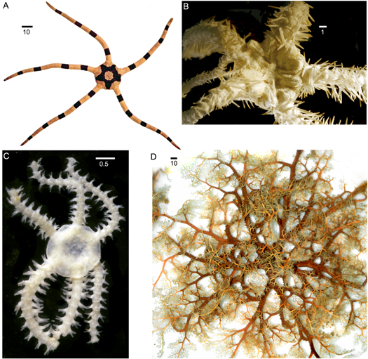
Figure 1. Diversity of brittle stars: A. Ophiolepis superba , a typical five-armed form with simple arms; B. Ophiacantha enopla veterna , a form with long serrated arm spines and spinelets covering the disc; C, Ophiactis tyleri , a six-armed fissiparous form; D. Euryale aspera , a basket star with branched arms Scale bars in millimetres. Reprinted with permission from [ 1 ] (CC-BY).
Download figure:
The challenge in developing brittle star inspired pentapod (5-legged) robots is, therefore, in coupling the mechanical design of a functional tough exterior/soft interior composite leg with viable high DoF motion control. The benefits of such a configuration is to allow the coupling of desirable aspects of soft robotics with those of hard exterior robots. The combination of these features means that the robot can morph its shape with higher degrees of deflection than that of a rigid bodied robot, and has additional benefits in dynamic mechanical or impact energy dissipation, due to there being a flexible continuum. The coupled rigid exterior enables the robot to be used in environments and under conditions where a soft flexible robot body may suffer from external damage such as punctures from contact with sharp objects. The pentapod is a unique area of robotics that has received considerably less attention than other n-legged robots such as bi-, tri-, quadru- and hexapods [ 3 – 6 ]. Actuation control in pentpodal robotics is not always trivial. There are a number of factors to consider including the large numbers of possible forms of gait, methods for actuation, the suitability of the mechanical design of the limb in terms of both limb-loading and kinematics, the actuation mechanism for an individual limb incorporating high DoF, and sense-response mechanisms devoted to motion control. Jin and Dong [ 3 ] considered Shape Memory Alloy (SMA) actuation systems for starfish inspired pentapods with limited DoF. Their pentapodal robots had modular legs that were mechanically designed to actuate in only one axis. This is not as versatile as the actual starfish and the design therefore has obvious limitations in terms of bioinspired gait.
Some mechanical designs make use of a decentralised control system like that of the brittle star [ 5 , 6 ] where the arms make use of two to three servos per arm to control the vertical and horizontal motion of each leg. In [ 5 ] and [ 6 ] each leg uses an individual Proportional Derivative (PD) controller and a pre-determined motion path for the gait. As evidenced by [ 6 ], stability analyses for 22 gait combinations, a 3 × 2 gait sequence is optimal for pentapodal speed. Research into climbing gaits [ 7 , 8 ] has been conducted to optimise pentapodal climbing, but it cannot be assumed that this transfers naturally into walking gaits. Performance metrics for various n-legged gaits demonstrate that soft-body starfish inspired robots [ 4 ] are unable to move as effectively as other n-legged robots [ 5 ]. However, they are less complex in terms of gait sequence and because they are pentapodal, they have a large variety of gait sequences that may be of benefit for other-than flat terrain walking situations.
Starfish-inspired robots are either soft-body SMA actuated robots, or, are fully rigid hard body robots. The closest robot to bridging the gap between these, offering higher levels of dynamic motion to that of current soft-body robots is PATRICK [ 4 ]. This robot has an untethered design, utilising two SMA actuation wires in a highly flexible silicon limb to generate more complex motion paths than other soft-body robots. PATRICK is one of the first untethered brittle star inspired underwater robots that in real-time varies its locomotion. Almost all of the compute for PATRICK is executed remotely on a laptop, so the robot is less viable for real world applications without a remote laptop connection. Displacement over time metrics are also given for PATRICK, and it can be noted from these metrics that the robot performs well for its relative scale and soft-body make up. It appears that [ 4 ] is the only work to propose a closed-loop trajectory planning method of motion primitives in a 5-legged robot. One of the key areas of improvement mentioned is to move the compute on-board the starfish so that it can be used in a non-lab environment.Along with this, it is important to note that PATRICK needs to operate under water due to the cooling requirements of the SMA wires, meaning it would not perform to the same level out of water if the temperatures are sufficiently high to prevent the effective utility of SMA wires. A key short-coming of the mechanical design of PATRICK is that of inter-limb variance. This was noted to be due to the limb force output and displacement being sensitive to differences in manufacturing. In addition, the SMA wires coupled with the silicon limbs introduce a level of significant non-linearity to the system.
Effective position control is a function of system mechanics, material properties, the method of actuation and the accuracy and speed of sense-response mechanisms during actuation. The robotic limb reported in this communication considers all four functions. Our aim is to design a brittle star inspired mechanical limb with high degrees of motive freedom enabled by minimised numbers of actuators. The robotic limb will, like the brittle star, combine a hard exoskeleton with a soft and flexible internal segment to enable a shared material, composite response to actuation. Finally, a Hall effect sensor system will be designed as an integral part of the limb itself, as we hypothesise that this will minimise position control errors that may ordinarily arise from mechanical losses during actuation and inaccurate controller feedback. Our hypothesis is based on that Hall effect sensors have already been shown to be effective in soft appendage robotic control. Proprioceptive sensing in soft limb robots for example [ 9 ], has been improved through modifications of the Hall effect curvature sensor alongside modifications to the actuation chamber cross section, which if soft, requires advanced flexible sensing mechanisms such as has been reported in [ 10 ]. Soft actuating limbs using groups of three-linear sensors are known to enable a high level of accuracy in soft robotic limb movement in flexure [ 11 , 12 ] and as such, are considered in this work to also have potential for the soft-hard composite appendages intended in this work.
2. Materials, Methods and Design Philosophy
2.1. mechanical design.
Mechanical design was driven by two main parameters, a soft-body level of bending and curvature with a harder exterior (like the actual brittle star), and reliable motion to improve on designs described in existing literature. Due to mechanical limitations in existing brittle star inspired designs, inspiration was sought elsewhere, including both the actual brittle star and other areas of robotics. 3D brittle star models [ 2 ] have enabled researchers to gain a deeper understanding of the mechanical structuring of the limb. The structure is essentially made up of discrete segments that interconnect via a ball and socket-like joint. Connective tissues and ligaments maintain the position and interlocking of the limbs. The use of repeat segments in the brittle star limb allows it to exhibit high degrees of curvature and mobility. The robotic structure mimicked herein and rendered in CAD, figure 2 , uses a flexible corrugated polypropylene pipe allowing for high degrees of deflection in Euclidean space [ 13 , 14 ]. FDM printed PLA exoskeletal segments are slipped over the polypropylene pipe and interlocked to mimic the exterior interlocked brittle star structure inferred from [ 2 ]. Segment to segment interlocking aids mobility in the exterior skeleton through its simple design, which is a tapered end interlocking protuberance from one segment that is inserted into the opening of an adjacent segment. Once inserted, the interlocking mechanism has a high degree of rotational freedom, similar to that of a ball and socket joint. The Hall effect sensors shown in figure 2 are embedded into external segments, and these are used to monitor movement. Further details on the sensor feedback is provided in section 2.3 .
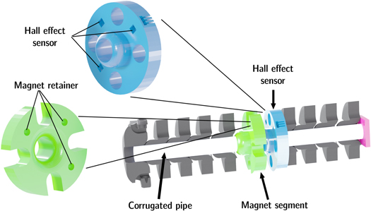
Figure 2. Cross sectional view of the final limb design.
2.2. Actuator Design
Inspiration was drawn from continuum style robotic manipulators [ 15 – 17 ]. A continuum robot relies on a bendable and often compliant central core, which in the case of our design is a polypropylene corrugated pipe described in section 2.1 . The single rod core design was pioneered by [ 18 ] and has the benefit of enabling non-complex deformation under loading.
Actuation in our design, figure 3 , relies only on two actuators to achieve a full range of motion, an improvement to the commonly seen set of three. To keep the arm itself light and small we selected an extrinsically actuated continuum [ 19 ], figure 4 . The use of a GT2 timing belt driven design as opposed to a metal or polymer pulley [ 20 ] ensures there is a reliable connection between the leg and actuator with minimal slip or mechanical losses. The driven belt allows for a single pulley wheel to pull the continuum arm in the two primary directions along a single plane, figure 5 . Doing this with two orthogonally oriented pulley wheels enables a full envelope of actuation with only two actuators. The use of two actuators on a toothed driven belt analagous to a tendon is a novel concept in continuum robotics, as many existing designs rely on a polymer pulley, and often, on more than two actuators to achieve the same DoF as we have in our design [ 17 , 21 , 22 ].
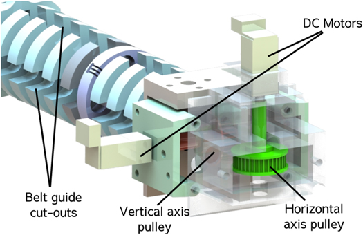
Figure 3. Actuator unit with two DC motors for the vertical and horiz.
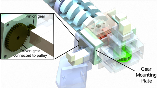
Figure 4. CAD model of the revised design.
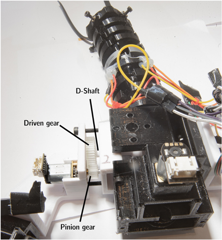
Figure 5. Gear system in place on the robot.
2.3. Hall Effect Sensor Feedback
A key component in dynamic robot design is the accurate feedback of limb positions to the controller for improved control of the limb in its inertial state. A Hall effect sensor position feedback solution, similar to that of [ 23 ], for the end point of the leg was implemented to provide the robot with useful limb-endpoint information. The application of this configuration in a hard-exterior limb is a novel application of the Hall effect array. Due to the nature of soft robotics, determining the orientation of a soft-bodied limb is difficult due to the infinite possible passive joint positions [ 24 ]. Similar work done on soft robot curvature presented by [ 25 ] and [ 26 ], uses a single Hall effect sensor to measure out of plane bending. Here, we use a 3 × 3 array of Hall effect sensors to feedback position. Similar systems have been used to monitor loading and unloading of spinal columns [ 27 ] and in orientation resolution of a spherical actuator [ 28 ]. Since Hall effect sensors and sensor arrays have been shown to have high accuracy for distance/orientation measurement [ 25 , 28 , 29 ], the use of Hall effect sensors in the continuum limbs of our robotic limb offers a small form factor but with the potential for high accuracy.
2.3.1. Orientation Resolution
The GT2 timing belt in our design connects the actuator to the limb and as such, slip is a possibility in any situation that may drive a force overload. A magnetic encoder such as used in [ 22 ], attached directly to the drive shaft of the actuator would not be able to provide sufficient information on the position of the limb in our design and furthermore require a calibration loop, and thus unable to offer absolute orientation of the limb in a continuum limb. Three points can be used to define a plane and as such, three Hall effect sensors is the minimum possible number that can be used to derive information on the planar orientation of the limb segment containing the sensors. This feedback arrangement relies on the assumption that the planar orientation of the middle section can be extrapolated to provide information on the end point of the limb. Our control system differs form that of previous work [ 4 , 30 ] in that they used single value decomposition with a proportional integral controller to provide orientation control to an SMA actuated soft limb.
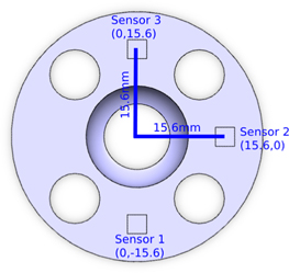
Figure 6. Hall effect linear distance sensors and their relative position.
Two vectors are created using the real-time measurements from the Hall effect sensor, and are given as z n where n corresponds to the sensor number the respective measurement is taken from according to figure 6 .
The angles between the normal vector and its two constituent vectors can be found, these angles, as demonstrated in figure 7 , are ψ and θ . Where ψ denotes the axis from sensor 2 to sensor 1, and θ the axis from sensor 2 to sensor 3.
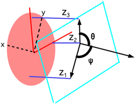
Figure 7. 3D representation of the sensor arrangement, with z 1−3 representing the respective distance measurements from the Hall sensor, θ representing the angle of the vertical axis, and ψ the horizontal.
The simplified deflection model shown in figure 8 shows how the orientation from the sensor readings can be used to find the end point location in one dimension.
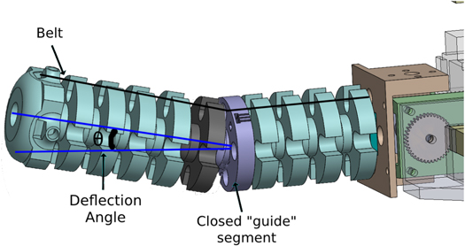
Figure 8. Simple model of limb deflection in one axis where the 'closed' segment acts as the bending point.
2.3.2. System Dynamics
With the method of feedback established, the actuator dynamics was introduced to enable limb control. A desired end point will be provided in spherical coordinates, as denoted by θ p and ψ p . The error in the current state of the arm and the desired state can then be given as in equation ( 7 ), with the same equation being used for ψ .
Similar to the work done in [ 30 ], the deflection of the arm can be estimated using Euler-Bernoulli beam mechanics, where the arm is represented as a cantilevered beam. The true system dynamics are complex, as the arm moves the vector of the pulling force F changes relative to the arm. To simplify this, the motion is simplified to one dimension; the force applied is broken down to a vertical component ( F y ) acting as a point load at the tip, and the horizontal component ( F x ) acting as an end moment, as demonstrated in figure 9 . This is then linearised around the point of investigation (denoted p ), equation ( 8 ).
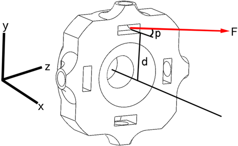
Figure 9. Force of the pulley on the end segment (denoted F ) at the distance from the neutral axis of the pipe (denoted d ) at fixed point p .
The offset of 90 is introduced to the control signal outside of the plant. A PI controller is introduced as H ( s ), equation ( 10 ).
Where k p is the proportional gain and k i the integral gain. Row 1 has the gains multiplied by a factor of 0.375 as the force output of the vertical motor is over twice that of the horizontal, allowing the system to be tuned once. The dynamics of the appendage is not only a function of the mechanical parameters but is also affected by the control parameters. Here, our focus is on evidencing an accurate mechanical response based on a novel Hall effect sensor system and we therefore maintain consistent control parameters to more effectively detail these mechanical responses.
2.3.3. Controller Implementation

Figure 10. Block diagram of the feedback controller for a single leg.
The block diagram above was modelled in MATLAB's simulink utility and the PI controller tuned. Controller response to a step response input, such as noise from the analog Hall effect sensors, was verified. Non-linearities in the model were introduced to ensure the sim-to-reality differences are minor.
2.4. Numerical Simulation
A numerical model was developed to provide additional validation on the accuracy of the analytical model. As previously established, the singular leg can be simplified into a planar model. The left side of the model has a closed off section that represents the interface between the actuator housing and the corrugated pipe continuum. This is the fixed point condition of the limb, as shown in figure 13 . At the height of the pulley a point load was applied in the - x and + y direction to approximate the components of the force vector from the pulley will load the beam. The model was discretised using Lagrange quadratic elements and a linear elastic analysis solved using a direct UMFPACK. A final mesh consisting of 268 480 elements was deemed appropriate for the simulations following a mesh convergence analysis. Polypropylene was modelled with a Young's modulus of 3.275GPa, while the PLA was modelled with a Young's modulus of 2.9GPa. A point load was applied based on equation ( 8 ) and the base-end of the limb was assigned a Dirichlet condition (0 DoF). A force of 21N was thus applied to achieve a deflection of 30°. The individual forces in the x and y directions from this point give a resultant force of 21N 30° from the loading point. The plane stress model was generated using the underlying constitutive plane stress equation, equation ( 12 ), where σ 11 and σ 22 are normal stresses in orthogonal directions, σ 12 is the shear stress relative to these directions, nu is the Poisson's ratio, ε 11 and ε 22 are normal strains in orthogonal directions, and ε 12 is the shear stress relative to these directions.
2.5. Pentapod robot locomotion
A whole body controller (WBC) and gait scheduler was developed to enable advanced robot locomotion. End-point limb control was used in accordance with a holistic controller and motion planner for dynamic motion of the robot. A BMI088 inertial measurement unit (IMU) was attached to the central body to measure the inertial state of the robot, the body axis for which is shown in figure 11 . This measures the angular rate around 3 axis and the linear acceleration in those 3 axis, equations ( 13 ) and ( 14 ), where v gyro has 3 measurements, the angular velocity, around x , y , z axis, and the same with v accel where the 3 measurements are the linear accelerations in each direction. Utilising concepts from [ 32 ], the absolute orientation of the IMU can be determined by the use of quaternion vectors and a basic gradient descent loop. As described in [ 32 ], A quaternion is a four-spatial-dimension complex number that can be mapped into three dimensions to track orientation, equation ( 15 ). The advantage of quaternion orientation representation is the removal of gimbal lock, which enables a higher range of orientation conditions >90°, if the need arises.
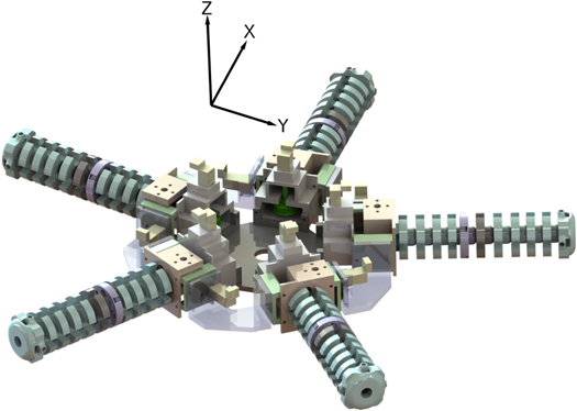
Figure 11. Body axis of the prototype robot.
The introduction of the accelerometer is described in length by [ 32 ], for context, equation ( 18 ) shows how the accelerometer is introduced alongside the estimated quaternion from equation ( 17 ).
The Euler angle representation of the robots orientation can now be described by converting from quaternion representation to Euler angles. These are denoted by Φ, Θ, Ψ, which are the body orientations around the body axis Z , Y , X (in accordance with figure 11 ).
Gait scheduling was developed in accordance with that of the natural brittle star based on the work by [ 5 ] and [ 2 ], with minor modifications made to suit the kinematics of the system and to optimise gait performance. The observations of brittle star locomotion documented in [ 5 ], shows that the brittle star primary mode of locomotion is singular limb by singular limb. However, various video documentations [ 33 , 34 ] also indicate that when swimming or traversing terrain at speed, a gait sequence similar to that shown in figure 12 (c) is used, where the black rectangles represent the full cycle of motion as angles around the two limb axes, as shown in figure 12 . This formed our initial proposed gait.
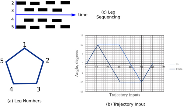
Figure 12. (a) Simplified view of each leg and its index number, where leg 1 aligns with the X body axis (b) the trajectory input in the two axis fed to the indvidual leg controller (c) diagram demonstrating the timing of the legs with respect to each other.
3. Results and discussion
The limb deflected to a maximum of 66.93 mm from the numerical simulation results under a load of 21N, figure 13 and the resultant angle was 28.55°, which is within 2° of the expected 30° (i.e. 96% accuracy). In this figure, von Mises stresses are noted increase from tip to base, and reach a maximum of 4.24 MPa in the polypropylene, which is far below its yield strength of >12 MPa, evidencing that limb deformation remains elastically recoverable throughout its actuation cycle.
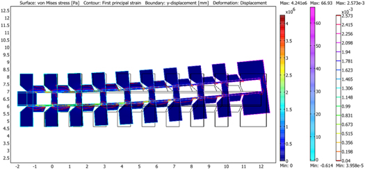
Figure 13. Finite element model mapping von Mises stresses during planar deformation of the limb.
Quantifying the performance of the individual limb controller is vital to achieving more complex motion primitives and to the development of the body orientation controller. The controller designed and proposed by [ 30 ] was found to have an accuracy of 5.18° and 2.93° for the pitch ( θ ) and yaw ( ϕ ) error, respectively. Here, the limb was calibrated at a neutral position, figure 14 . The vertical axis was provided a step input of 20°, and the horizontal axis given a reference signal of 0. The limb was filmed at 1000 Frames Per Second (FPS) with a 5mm reference grid background using a Chronos 1.4 (Krontech) high speed monochrome camera. The high speed footage allowed us to find the exact frames where the maximum and final deflection angles occured. These frames were then saved and the angle of the marker (white cone structure pictured in figure 14 ) recorded via the ImageJ software. Using this, an external measurement could be made to verify that the controller was performing as expected. This angle was measured in reference to the neutral position initially recorded, as that is what the feedback system deems as 0°. The micro-controller connected to the sensors recorded the sensor array derived angles, θ and ψ . The PWM control signal for both motors was also recorded. This data was recorded at 50 kHz on the micro-controller. This process was repeated 8 times for a step response to +20°, and the same again for −20°.
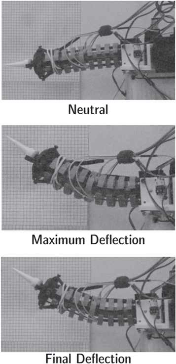
Figure 14. The original calibration reference (neutral) and the maximum and final deflection taken from trial 1.
From the plot (cf figure 15 ), the step response can be observed to be in line with what was expected. There was slight overshoot, but it reaches the steady state target within 10 000 cycles (0.2s). The limb was notably slower than expected at travelling between 0°–2.5°, a trend that was consistent with the other trials. This is likely due to assumptions made in the controller model that are different in real life. For example, the initial forces mean there is little vertical component, due to how the belt is fed through the arms it is pulling predominantly axially along the continuum until the angle of the belt begins to separate from the angle of the limb. This can even be observed in the final deflection of figure 14 , where the gap between the belt and the limb appears larger than the neutral belt position. The individual segments of the appendage's connected exoskeleton are able to freely rotate and as such the belts when tensioned as the motor torques (2.9 kg ·cm) enable realignment, and as such, the belts can reset themselves to the axis of the limb without disrupting the dynamics and accuracy of the appendage beyond an initial static movement. The PWM control signal at the initial portion of the curve is saturated, and because this response is a result of the system mechanics it is difficult to remedy. The overshoot could be fixed by varying the gains for less overshoot, but it is likely this would be at the cost of an aggressive response. Table 1 , shows the difference between the desired angle and the final measured angle as observed from image analysis (Image J), along with the difference between the final measured angle and the measured angle. The former serving to validate the steady state error of the controller, and the latter to validate the sensor feedback method. The average steady state error of the step response is 1.895, a 2.7 × steady state error improvement to the control work proposed in [ 30 ]. This highlights two key benefits to the proposed continuum limb, the limb is able to be modelled and controlled without the need for a SVD compensator and the sensor feedback mechanism offers useful and accurate information for the controller. The design and experimentation demonstrated here elucidates an alternative method for actuating soft-bodied robots that improves accuracy relative to the current reported methods for actuation.
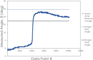
Figure 15. Measured angle for a 20° step input. Here, 10 000 cycles = 0.2s.
Table 1. Error Data for the 8 trials with input +20°.
From the collection of all trials, figure 16 , all curves notably share similar shapes in both the positive and negative direction of motion. This indicates that the limb moves consistently upon step input requests. To validate this, we calculated the root mean squared error (RMSE) between the two most extreme curves (fastest initial response compared to slowest initial response). This is between the first and sixth trial in the positive direction. The RMSE was found to be 0.057. For the negative direction, trials 7 and 8 were compared and the resulting RMSE was 0.023. This indicates the curves are consistent with each other for a step response input of +20° and −20°. However, there is an observable difference between the shape of the positive and negative curves. The leg is essentially fighting gravity in the positive direction, whereas in the negative direction, the mass of the arm contributes to motion, behaviour that is not accounted for in the controller. Further work could be done to incorporate the mass of the arm segments as point masses along the arm that contribute to the inertial response of the arm under motion. In the context of the entire robot, the vertical axis of the limb will be responsible for lifting the robot, so it is anticipated that the curves would look different under a true loading scenario, but this experimentation serves to validate the Hall effect feedback mechanism and validates the consistency of the feedback loop to step response inputs. Figure 17 shows video frames taken at 10 second intervals from a video recorded using a Chronos 1.4 monochromatic video camera run at 1000fps. Table 2 provides some insight as to how the proposed design compares to existing both untethered (PATRICK [ 4 ]) and tethered ([ 5 ] ) starfish inspired pentapod robots. In particular, we compare the velocity, weight and the momentum of each robot. The tethered robot from [ 5 ] unsurprisingly has the highest power and hence develops the highest momentum. PATRICK like the pentapod developed in this work, is an untethered pentapod. While PATRICK has a marginally higher velocity than our pentapod, it is also significantly lighter and as such, our robot exhibits a 3.7 times value for momentum than PATRICK.
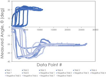
Figure 16. All step response trials, 8 trials to +20° and 8 trials to −20°.
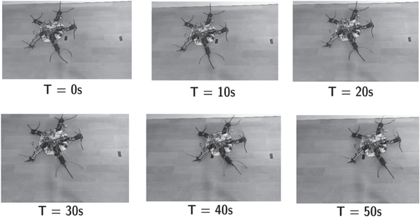
Figure 17. Displacement of the robot for a 50 cm distance over time.
Table 2. Comparison of displacements over time for brittle star inspired robots to the pentapod design from this work. Here: v is velocity, w is the weight of the robot and m is the momentum expressed by w × v .
4. Conclusions
The results presented in this paper indicate the method of resolving orientation using a Hall effect sensor array configuration is effective. The data indicates the sensor is within 2° accurate at measuring the deflection angle of the leg for positions within a range of −20° to 20°. This holds promise for the use of such a system in other continuum robotics. Current solutions for feedback control in continuum robotics measure the position of the drive motor, which relies on there being no slip between the drive and the continuum. This is, however, not the case when the continuum robot is under load since the sensors are integrated within the limb, they only take into consideration true limb motion, suggesting therefore, that the sensor array proposed herein, is a viable and effective method of resolving orientation in a continuum robot. When tested as a pentapod robot for velocity and momentum, we find that the pentapod developed in this work has a lower velocity than another untethered pentapod (PATRICK) however, it is also significantly heavier and as such, its momentum is 3.7 fold higher than that of PATRICK.
Data availability statement
The data that support the findings of this study are available upon reasonable request from the authors.
An Overview of Hall Effect Sensors Research Paper
Introduction, applications, works cited.
Hall-effect technology was first discovered in 1879. It was discovered by a physicist who was trying to prove the theory of electron flow (Ramsden 12). The physicist, Dr. Edwin Hall, discovered that a magnetic field affected the flow of current in a gold rectangle that was placed perpendicular to the magnetic field. This discovery gave rise to the advent of hall-effect sensing technology. Hall-effect sensors are devices that are magnetic and are used either to measure magnetic fields or as magnetic switches. This technology is often employed in speed detection, current sensing, positioning, and proximity switching. Hall-effect sensors are designed using basic engineering principles and are used in various applications.
Basic hall-effect sensors operate as magnetic field sensors. For them to be usable in various applications, they require signal conditioning. This conditioning includes an amplifying stage and some temperature compensation. If the voltage used is uneven, then there is a need for voltage regulation.
A basic hall-effect sensor consists of a regulator, hall element, a differential amplifier, and voltage input. This type of sensor is an analog device and it produces a voltage equaling its magnetic field. The magnetic field that is produced in this sensor can be either positive or negative. This means that the amplifier records both plus or minus power supplies. Hall-effect sensors are available in a variety of voltage ranges. There are 4.5 to 12, 4.5 to 10.5, and 6.6 to 12.6 VDC sensors. The transfer function of these sensors can be expressed through an equation or a graph. The transfer function value in this case is determined by null-effect, sensitivity, and span.
Digital output sensors on the other hand consist of a regulator, amplifier, Schmitt trigger, and a regulator. Its transfer function incorporates hysteresis and current sinking. Digital sensors can use regulated or unregulated power supplies. Their output depends on operation point, differential, and release point.
Hall-effect sensors are applied in various devices and mechanisms. The choice of application is primarily based on the operating and release characteristics of the sensor. Some of these applications include vane-operated sensors, gear tooth sensors, current sensors, and magnetically operated switches.
Vane-operated power sensors use both a magnet and a digital hall-effect sensor. These are all placed in a non-magnetic material. There is a gap left for a vane to pass through. This type of sensor is designed to detect the presence or absence of this vane. Any obstruction to this vane activates the sensor and it goes on. When the vane is present again, the sensor will go off. This mechanism also works in reverse when detecting the presence of a vane.
The other common application of hall-effect sensor technology is in gear-tooth sensors. This sensor is designed to sense the movements of metal targets. The gear tooth concentrates magnetic influx into the sensor as it passes through a field. This prompts the sensor to detect this change in influx hence switching it on.
Linear current sensors are made using silicon steel and hall-effect sensors (Kato 1912). These are put together in plastic housing. These sensors are designed to monitor the amount of magnetic flow a current produces as opposed to measuring the actual current flow. These field changes are monitored in the form of waves. This measurement helps determine when there is saturated voltage hence cutting it off.
Hall-effect sensor technology has pioneered many other similar technologies. However, its basic designs and operations are still used in various engineering designs and principles. This technology may still be improved in the future.
Kato, L, et al. “Observation of the Spin Hall Effect in Semiconductors.” Science 306 (2004): 1910- 1913. Print.
Ramsden, Eddie. Hall-effect sensors: theory and applications , New York, NY:Elsevier, 2006. Print.
- Chicago (A-D)
- Chicago (N-B)
IvyPanda. (2022, May 1). An Overview of Hall Effect Sensors. https://ivypanda.com/essays/an-overview-of-hall-effect-sensors/
"An Overview of Hall Effect Sensors." IvyPanda , 1 May 2022, ivypanda.com/essays/an-overview-of-hall-effect-sensors/.
IvyPanda . (2022) 'An Overview of Hall Effect Sensors'. 1 May.
IvyPanda . 2022. "An Overview of Hall Effect Sensors." May 1, 2022. https://ivypanda.com/essays/an-overview-of-hall-effect-sensors/.
1. IvyPanda . "An Overview of Hall Effect Sensors." May 1, 2022. https://ivypanda.com/essays/an-overview-of-hall-effect-sensors/.
Bibliography
IvyPanda . "An Overview of Hall Effect Sensors." May 1, 2022. https://ivypanda.com/essays/an-overview-of-hall-effect-sensors/.
- Raman Amplifiers and Their Advantages and Disadvantages
- Digital Feedback Control System of Automobile Engine
- The Concept of Memory Palace: Discussion
- Radio Over Fibre or Fibre Wireless Systems
- Fiber Optics Usage in Medicine
- Systems Analysis and Design: Smartcards
- Global Positioning System Technology and Security
- Condenser Operation and Maintenance

IMAGES
VIDEO
COMMENTS
In particular, this manuscript focuses on Hall-effect sensors realized on standard silicon technologies, and it reviews some typical architectures for the transduction of the measurand current into a magnetic field, as well as the electronic front-end. While this tutorial is mainly addressed to students and non-expert readers, specific design ...
1.1. Hall Effects—Brief History and Evolution. The Hall Effect is a well-known and established phenomenon since it was discovered by Edwin Herbert Hall (1855-1938) in 1879 [1,2], while he was a graduate student under the supervision of Henry Rowland (1848-1901) at the Physics Department of Johns Hopkins University.One hundred years later, on 13 November 1979, a symposium was held at ...
The objective of this paper is to review the available configurations and current status of the Hall effect-based technologies. A detailed discussion is carried out on the various types of existing Hall-based devices, such as linear sensors, field-programmable sensors, switches, latches, speed and directional sensors, and vane sensors.
Abstract and Figures. The present paper focuses on various aspects regarding Hall Effect sensors' design, integration, and behavior analysis. In order to assess their performance, different Hall ...
Feature papers represent the most advanced research with significant potential for high impact in the field. A Feature Paper should be a substantial original Article that involves several techniques or approaches, provides an outlook for future research directions and describes possible research applications. ... Hall Effect Sensors (HES ...
The present paper focuses on various aspects regarding Hall Effect sensors' design, integration, and behavior analysis. In order to assess their performance, different Hall Effect geometries were tested for Hall voltage, sensitivity, offset, and temperature drift. The residual offset was measured both with an automated measurement setup and by manual switching of the individual phases. To ...
3.1. Hall Effect Sensor Measurements In order to accurately test the Hall Effect sensors, an automated measurements setup has been built [6]. Previous papers in the literature were devoted to Hall sensors current measurements [10]. The nine integrated Hall cells are presented in Table 1. Part 1 of the table refers to the cross-like
Download figure: Standard image High-resolution image As will be explored in this review, even classical Hall effect sensors have a huge array of applications, and depending on the scale of the Hall probes, the selection of materials to fabricate Hall probes is almost limitless thanks to decades of industrial and academic research and development [].
Five different Hall Effect sensors were modeled and their performance evaluated using a three dimensional simulator. The physical structure of the implemented sensors reproduces a certain technological fabrication process. Hall voltage, absolute, current-related, voltage-related and power-related sensitivities were obtained for each sensor. The effect of artificial offset was also investigated ...
times better than the state-of-the-art. Research was con-ducted by the authors to predict Hall Effect sensors behavior by three-dimensional physical simulations [11] and guide the designer in optimal Hall sensor shape selection process. The current work is intended to analyze the temperature behavior of Hall Effect sensors current-related ...
Though it is widely acknowledged in the literature that the 2DEG Hall sensors based on AlGaN/GaN heterostructures can provide stable sensitivity over a wide range of temperature [25, 32, 42, 48-51], and very few commercial sensors are 2DEG based [52, 53]. These known commercial Hall sensors are also not based on AlGaN/GaN heterostructures.
where G is the geometric factor; t is the thickness of the Hall device; N is the impurity concentration of the device; r n is the Hall factor; q is the amount of charge per unit charge; I bias and B are the bias current and the applied magnetic field strength, respectively.. The magnetoresistance effect was discovered by Thomson in 1856. It refers to the phenomenon that when a magnetic field ...
Summary. Hall effect sensors measure the strength and polarity of a magnetic field. A Hall effect linear or rotary position sensor includes at least a Hall device, a position magnet, and associated electronic circuits. Hall effect sensing elements have a relatively low output voltage, so fabricating a position sensor requires the addition of an ...
A comprehensive review of the main existing devices, based on the classic and new related Hall Effects is hereby presented. The review is divided into sub-categories presenting existing macro ...
GMR sensors perform better than AMR sensors. Hall sensors have the least sensitivity and resolution; however, they make up for it by offering a high dynamic range at low cost. The low cost, adequate performance and high availability makes Hall effect sensor the most popular magnetic field sensor on the market . The best performance is offered ...
The results presented in this paper indicate the method of resolving orientation using a Hall effect sensor array configuration is effective. The data indicates the sensor is within 2° accurate at measuring the deflection angle of the leg for positions within a range of −20° to 20°.
Depending on the underlying principle of the field measurement, magnetic sensors can be mainly classified into the search-coil magnetometer, flux-gate magnetometer, giant magnetoresistance sensor, Hall-effect sensor and superconducting quantum interface device . Each technique has its advantages in a certain sensitivity range, though the latter ...
1) A Hall Effect sensor can be used as a magnetometer which measures the magnetic field. 2) Hall effect sensor is also used as current sensor. 3) Hall effect sensor is also used to automatically ...
This paper presents the design, development and evaluation of a unique non-contact instrumentation system that can accurately measure the interface displacement between two rigid components in six degrees of freedom. The system was developed to allow measurement of the relative displacements between interfaces within a stacked column of brick-like components, with an accuracy of 0.05 mm and 0. ...
Hall-effect sensors are devices that are magnetic and are used either to measure magnetic fields or as magnetic switches. This technology is often employed in speed detection, current sensing, positioning, and proximity switching. Hall-effect sensors are designed using basic engineering principles and are used in various applications.
Hall effect-based tactile sensors are of particular interest in this application owing to their low-cost, small size, and high robustness. One complexity of the sensors is the relationship between the elastomer geometry and the measurement range. This paper investigates the design parameters of Hall effect tactile sensors for use in hand splinting.
Feature papers represent the most advanced research with significant potential for high impact in the field. A Feature Paper should be a substantial original Article that involves several techniques or approaches, provides an outlook for future research directions and describes possible research applications. ... Among all magnetic sensors ...